RTA Products RTA-B005 User Manual
Page 7
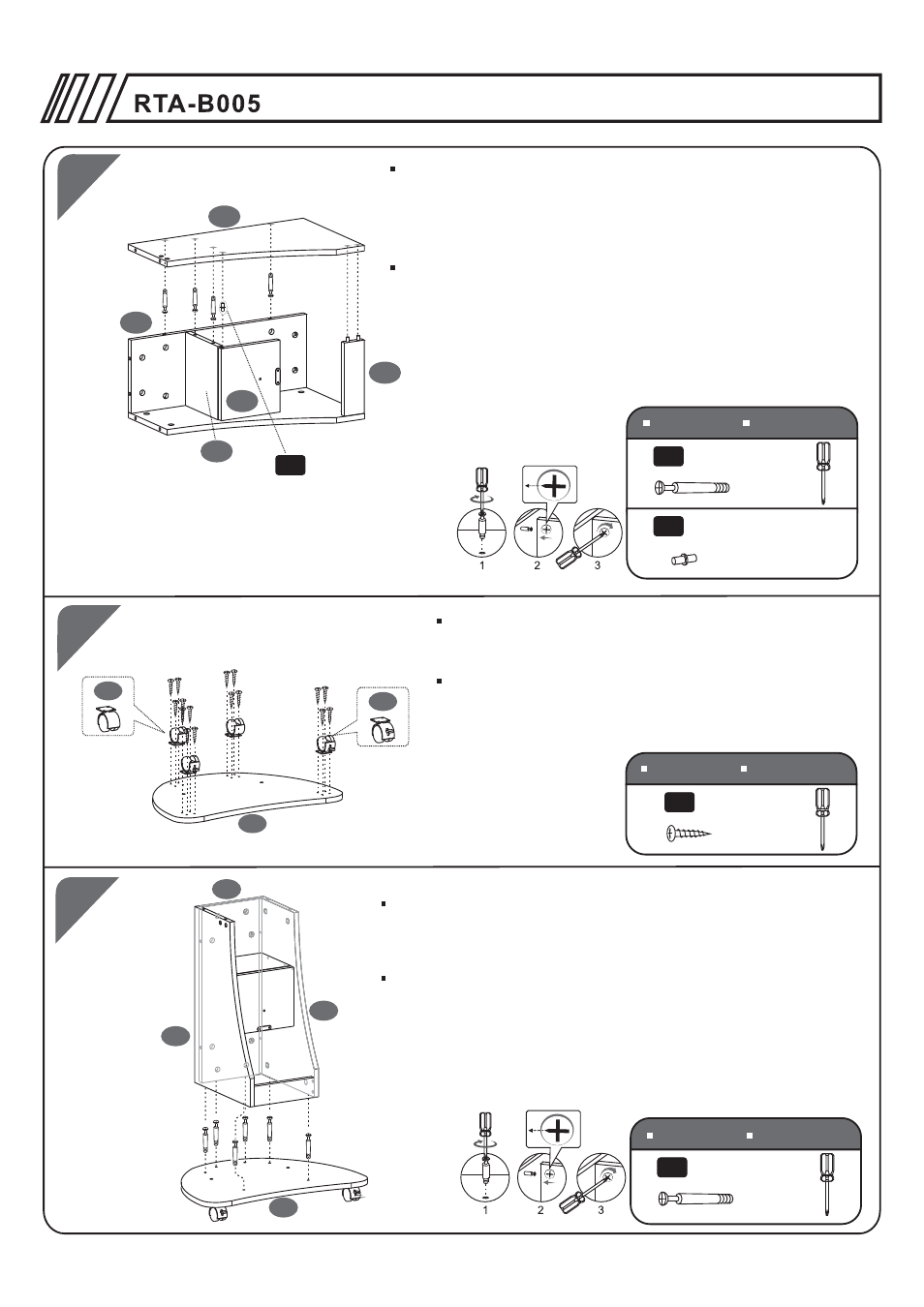
4PCS
6X40 MM
D
1PC
H
Φ5X17 MM
5
4
2
6
H
18
4
5
7
3
X2
3
X2
16PCS
4X14 MM
A
Screw Bolts (D) to the inside face of the Right Panel (2).
Insert the other double side Pin (H) into the hole of Drawer
Panel (18). Join the panel (2) with the semi structure built
in step 3, and make sure to turn all the corresponding cam
locks on panels (4) and (6) to secure the bolts.
SCREWS
TORNILLOS
SCREWS
TORNILLOS
Use Screws (A) to assemble the Casters (3) to the back
side of the Bottom Panel (7). Make sure the 2 locking
casters are facing to the front.
Con tornillos A fije las Ruedas (3) a la cara posterior del
Panel Inferior (7). Aseg rese que las ruedas con el cerraje
queden puestas en la parte de adelante.
ú
6
6PCS
6X40 MM
D
1
2
4
7
Screw Bolts (D) to the Bottom Panel (7). Then place the Left,
Right and Back Panels (1,2,4) over the Bolts (D) and secure
them tightening the connecting pieces in the Left and Right
Panel (1&2), the Back Panel (4).
Atornille los pernos (D) en la superficie interior del panel
Inferior (7) . Coloque los Los Paneles Izquierdo, Derecho y
Posterior (1,2,4) sobre los pernos (D) del panel Inferior (7)
Finalmente aseg relos girando los cerrojos en los paneles
posterior (4), lzquierdo (1) y derecho (2).
ú
SCREWS
TORNILLOS
P.7
Atornille los pernos (D) a la parte interior del Panel Derecho (2).
Inserte el otro pasador doble (H) en el hueco del Panel de
Gaveta (18). Junte el panel (2) con la semi estructura construida
en el paso 3, y haga girar los cerrajes correspondientes en los
paneles (4) y (6) para asegurar los pernos.