Installation – Desa CGEFP33PRB User Manual
Page 20
www.desatech.com
111245-01C
20
PRESSURE TESTING FIREPLACE GAS
CONNECTIONS
1. Open equipment shutoff valve (see Figure 27,
page 19).
2. Open main gas valve located on or near gas
meter for natural gas or open propane/LP
supply tank valve.
3. Place manual ignition switch in the OFF
position.
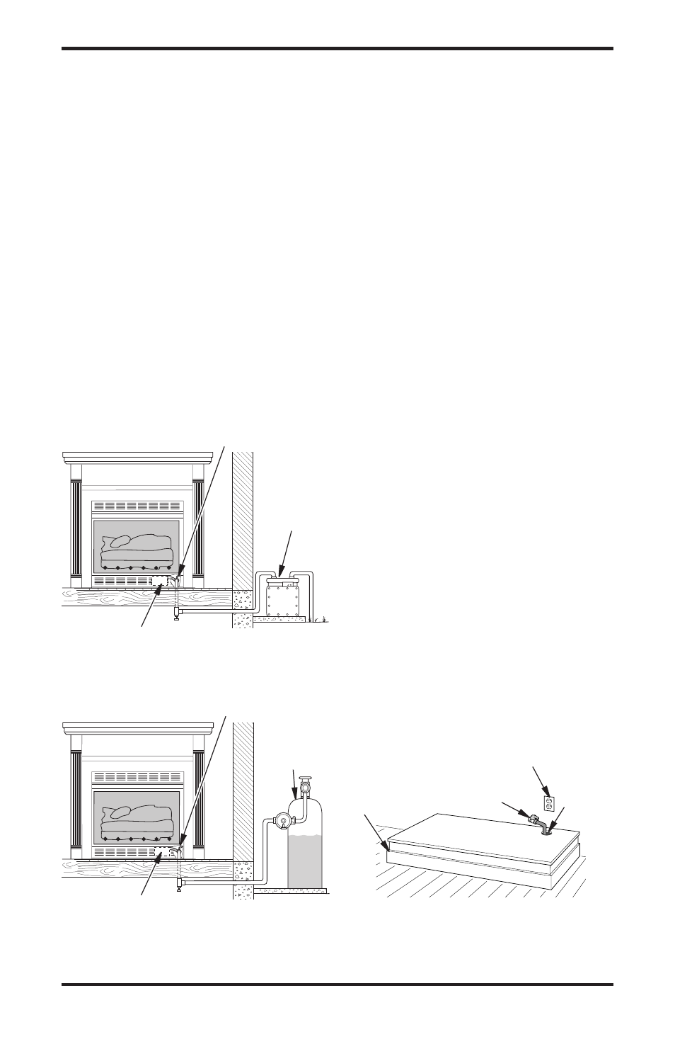
4. Check all joints from equipment shutoff valve
to gas valve (see Figure 28 or 29). Apply
noncorrosive leak detection fluid to all joints.
Bubbles forming show a leak.
5. Correct all leaks at once.
6. Light fireplace (see Operating Fireplace, page
25). Check all other internal joints for leaks.
7. Turn off fireplace (see To Turn Off Gas to
Appliance, page 27).
INSTALLATION
Continued
Figure 28 - Checking Gas Joints for
Natural Gas Fireplace
Figure 29 - Checking Gas Joints for
Propane/LP Gas Fireplace
Equipment Shutoff Valve
Manual Gas Valve
Gas Meter
Equipment Shutoff Valve
Manual Gas Valve
Propane/LP
Supply Tank
CONVENTIONAL FIREPLACE
INSTALLATION
Conventional installation of fireplace involves in-
stalling fireplace along with corner, face or cabinet
mantel with hearth base accessories against a wall
in your home.
Note:
Refer to instructions provided with the man-
tel for assembly instructions. Refer to the follow-
ing instructions for system installation. Refer to
instructions on page 23 for hood assembly. Blower
accessory should be installed prior to mantel if it is
being used (see Installing Variable Speed Blower
Accessory, page 13, or Installing Thermostatic
Blower Accessory, page 15).
1. Assemble cabinet mantel as shown in acces-
sory instruction sheet.
2. If blower is installed, install a properly
grounded, 120 volt three-prong electrical out-
let at fireplace location if an outlet is not there.
If possible, locate outlet so cabinet mantel will
cover it when installed (see Figure 30).
3. Place hearth base against wall at installation
location. Cut an access hole in hearth base to
run gas line to fireplace (see Figure 30). Make
sure to locate access hole so cabinet mantel will
cover it when installed. Note: You can secure
base to floor using wood screws. Countersink
screw heads and putty over.
4. Route flexible gas line through access hole in
hearth base.
5. Center cabinet mantel on hearth base (see Figure
31, page 21). Make sure mantel is flush against
wall and centered left to right on base.
6. Use screws provided with mantel accessory
to attach mantel assembly to base (see mantel
instruction sheet).
7. Attach flexible gas line to fireplace gas regula-
tor. See Connecting Fireplace to Gas Supply,
page 18.
Figure 30 - Placing Hearth Base
Accessory Against Wall
Electrical
Outlet
Hearth
Base
Rigid Pipe
and Gas
Shutoff Valve
Gas
Line
Access
Hole