Mcm installation – Parr Instrument Motor Control Module (MCM) User Manual
Page 5
MCM Installation
w w w . p a r r i n s t . c o m
5
Wiring Installation in 4848 Reactor Controller (Continued)
8. Find the remaining black wire #2 from the kit and attach one end to pin 1 on the 2084E meter. Take
care not to apply too much torque which could cause the wire to break. (This may already be con-
nected for your convenience.) The other end attaches to terminal block position #5.
9. Find the remaining white wire #1 from the kit and attach one end to pin 2 on the 2084E meter. Take
care not to apply too much torque which could cause the wire to break. (This may already be con-
nected for your convenience.) The other end attaches to terminal block position #2.
10. Find the black wire #5 (with one end stripped and one end has a snap spade terminal connector)
and attach the stripped end to the 2084E meter terminal #9. (This may already be connected for your
convenience.) The snap spade end attaches to the 1588E signal isolator terminal #5.
11. Find the red wire #6 (with one end stripped and the other end having a snap spade terminal at-
tached) and attach the snap spade connector to terminal #6 on the 1588E signal isolator. Attach the
stripped end to terminal #10 on the 2084E Meter.
12. Find the black wire #7 (one end has a snap spade terminal the other has a female quick disconnect
terminal) and attach the snap spade connector to terminal #9 on the 1588E signal isolator. The fe-
male quick disconnect attaches to terminal F- on the speed control board.
13. Find the red wire #8 and attach the snap spade connector to terminal #10 on the 1588E signal isola-
tor. Attach the female quick disconnect to the top position on the local/remote switch.
14. Disconnect the orange wire #10 at the speed control board terminal P2 and attach to the bottom po-
sition on the remote/local switch.
15. Find the orange wire #9 and attach one end to terminal P2 on the speed control board. The other end
attaches to the middle position on the local/remote switch.
16. Find the black wire #11 (with one end stripped and the other end has a snap spade terminal at-
tached) and attach the snap spade connector to terminal #4 on the 1588E signal isolator. Attach the
stripped end to terminal block #1.
17. Find the white wire #12 (with one end stripped and the other end has a snap spade terminal at-
tached) and attach the snap spade connector to terminal #1 on the 1588E signal isolator. Attach the
stripped end to terminal block #2.
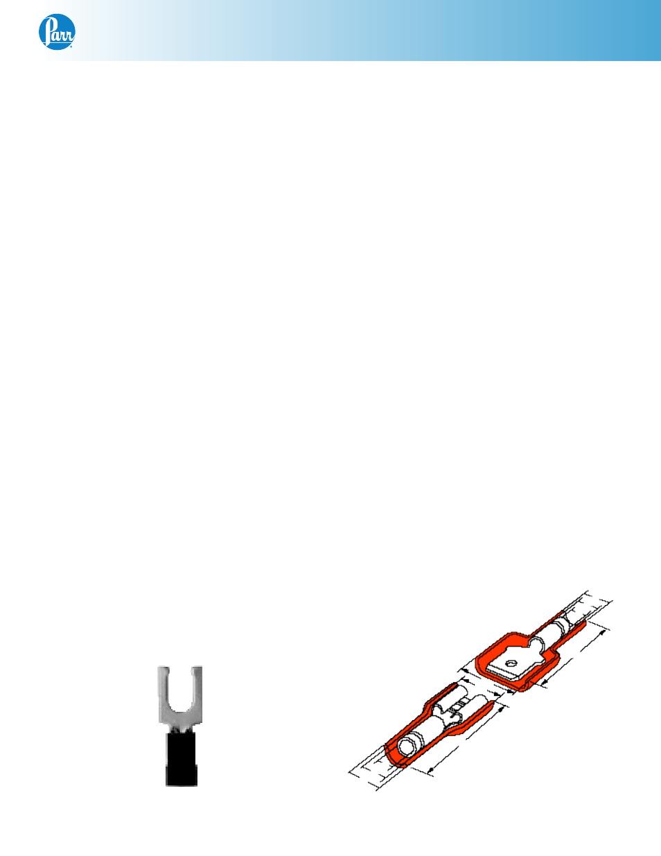
Snap Spade
Quick Disconnect Terminals
A
A
E
E
D
C
C
D
B