Mcm installation – Parr Instrument Motor Control Module (MCM) User Manual
Page 4
MCM Installation
P a r r I n s t r u m e n t C o m p a n y
4
7
8
9
10
11
12
1
2
3
4
5
6
2084E Pin Out
(Pin 5 is blank)
Wiring Installation in 4848 Reactor Controller (Continued)
4. Attach the 4-pin edge connector from the
A2106E to the “Tach In” (slot A). Align the empty
spot on the edge connector to the empty pin on
the “Tach In” of the A1695E excitation board.
Reference the A1695E Picture on page 3.
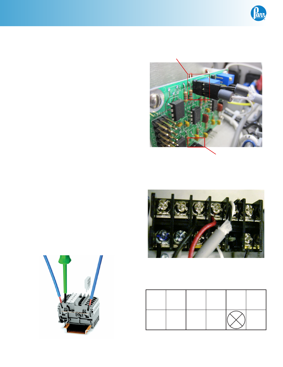
5. Find the 2 wire cable, black and white wires with
one end stripped and the other end has a 3 pin
edge connector as shown, and plug the 3-pin
edge connector to the “Tach Out” (slot A). The
Orientation of the black wire does not matter;
the connection can be plugged in either way.
6. The stripped end of the 2 wire cable attaches
to the 2084E meter. Take care not to apply too
much torque which could cause the wire to
eventually break. The meter’s pins are labeled
1-12, as shown. The black wire from the A2106E
harness attaches to pin 6, and the white wire at-
taches to pin 4. (This may already be connected
for your convenience.)
7. Find the 2 wire cable with white and black wires
that has both ends stripped, and attach one end
to the 2084E meter. White wire #3 to terminal
#11 and black wire #4 to terminal #12. (This may
already be connected for your convenience.)
The other end of the white wire #3 attaches to
terminal block position #4 and the black wire #4
attaches to terminal block position #3.
Note:
The terminal block position can be opened
up using a small flat head screw driver to release
the tension from the spring inside the block so you
can press the wire against the spring.
Wago Terminal Block
TACH OUT
TACH IN