A2200e rear panel, Installation, General instructions – Parr Instrument Model A2200E User Manual
Page 6: Inputs/outputs, General instructions — 6 inputs/outputs — 6, A2200e rear panel — 6, Flow controller
Flow Controller
P a r r I n s t r u m e n t C o m p a n y
6
Installation
General Instructions
Set the controller near the reactor on a sturdy bench
or table where there is convenient access to an
electrical outlet capable of carrying the appropriate
current. Leave a space of at least twelve inches
between the controller and the reactor so that the
controller will not be affected by radiant heat.
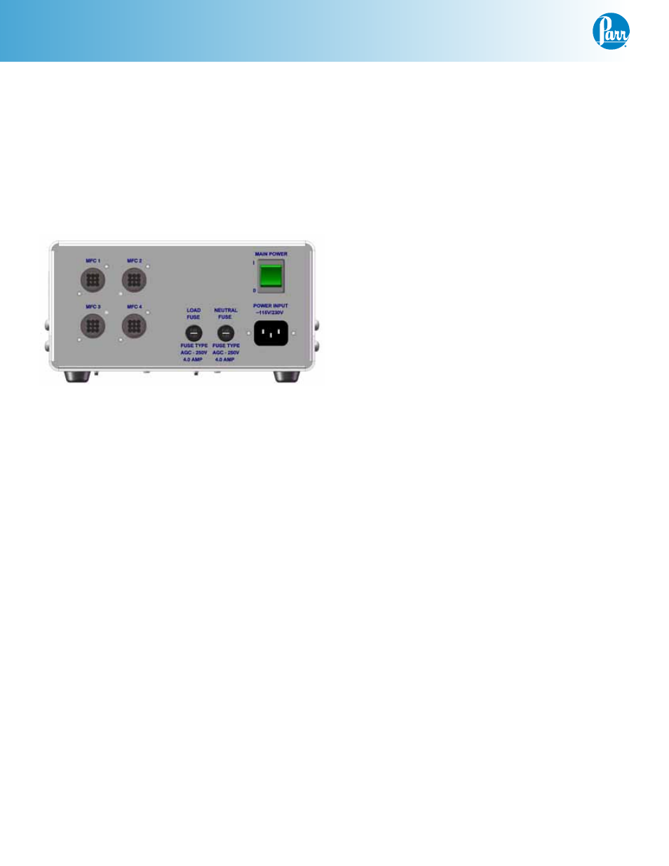
A2200E Rear Panel
Attach the supplied power cord to the POWER
INPUT connector located on the rear panel of the
A2200E Flow Controller.
Plug the power cord into a properly grounded
electrical supply outlet.
Inputs/Outputs
Up to 4 MFC I/O connectors and corresponding me-
ters can be supplied with each A2200E. The A2200E
I/O’s are to only be used with Parr approved control-
lers. The interface is designed for mass flow control-
lers which are specified during the ordering process.
An interface cable is supplied for each I/O.
With the A2200E powered off, attach the provided
I/O cable(s) to each MFC. Then attach the opposing
end to the A2200E Flow Controller.
If more than one MFC has been supplied it is recom-
mended that each I/O be identified as to which MFC
is connected.