Pin out table, Wiring schematic – Parr Instrument Primary Temp Meter User Manual
Page 2
- 2 -
PTM Installation in a 4848
Pin Out Table:
*White (Type – J), Yellow (Type – K), Blue (Type – T), Black (RTD)
**Red (Type – J, Type – K, Type – T), White (RTD)
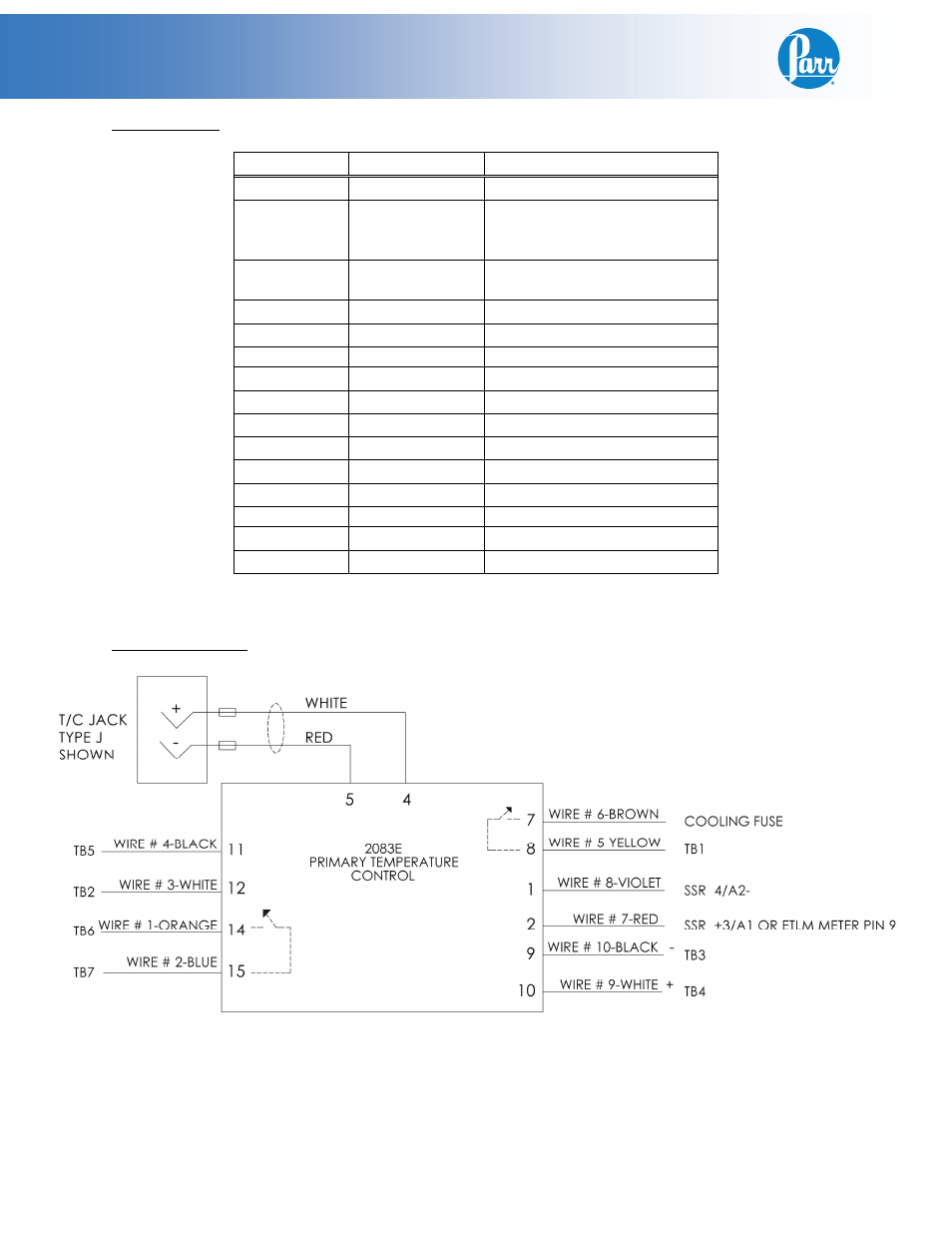
Wiring Schematic:
2083E Meter Color/Wire#:
Attaches to:
Pin 1
Violet/Wire#8
SSR 4/A2-
Pin 2
Red/Wire#7
SSR +3/A1 or
ETLM Meter Pin 9 (When
used with an ETLM Module)
Pin 3
Red (RTD
Only)
Thermocouple -
Pin 4
White*
Thermocouple +
Pin 5
Red**
Thermocouple - 1G
Pin 6
Pin 7
Brown/Wire#6 Cooling fuse (End)
Pin 8
Yellow/Wire#5 Terminal Block 1
Pin 9
Black/Wire#10 Terminal Block 3
Pin 10
White/Wire#9
Terminal Block 4
Pin 11
Black/Wire#4
Terminal Block 5
Pin 12
White/Wire#3
Terminal Block 2
Pin 13
Pin 14
Orange/Wire#1 Terminal Block 6
Pin 15
Blue/Wire#2
Terminal Block 7