Servicing the magnetic drive, Parr magnetic drives – Parr Instrument Magnetic Drive User Manual
Page 4
Parr Magnetic Drives
P a r r I n s t r u m e n t C o m p a n y
4
Servicing the Magnetic Drive
All non-wetted rotating parts in Parr magnetic drives
are permanently lubricated and do not require servic-
ing during normal operation. During operation, inspect
the magnetic drive for unusual noise or leakage. If
problems are encountered with these items take cor-
rective action. The magnetic drive has internal bearings
and thrust washers which require replacement over
time due to physical wear. Excessive lateral or axial
play in the stirrer shaft is an indication of worn bear-
ings or thrust washers. Labored rotation or excessive
debris inside the reactor cylinder also indicates a need
for maintenance. It’s difficult to recommend a time-
based preventative maintenance interval for the drive
due to the wide spectrum of operating conditions en-
countered. The experience of the laboratory should be
used to guide the need for preventative maintenance.
It is advisable to check the drive from time to time for
evidence of leakage into the confined space between
the inner and outer rotors. This can be done without
removing the drive from the vessel head and does
not require complete disassembly. While performing
maintenance or rebuilding the drive, the PTFE o-ring
that seals the top plug should always be renewed if the
plug is removed. To inspect the drive:
1. Remove the four socket head screws located near
the top of the outer housing and remove the top
cover from the housing. This will expose the plug
which aligns the inner rotor and carries the prin-
ciple O-ring seal.
2. Unscrew the plug, using a 264AC5 face spanner in-
serted into the two holes at the top of the plug while
holding the rotor firmly with a 264AC3 or 264AC4
pin spanner inserted into one of the holes at the bot-
tom of the assembly above the cooling sleeve. With
the plug removed, the sleeve bushing and thrust
washer at the top of the rotor will be exposed.
3. Check for any evidence of leakage past the O-ring
seal. If vapors from the reactor have produced
solid deposits in or around the rotor housing, the
deposits will have to be removed to keep them
from destroying the slide bushings or jamming the
rotor. If cleaning is not re quired, replace the plug
and close the drive.
4. If cleaning is required, the inner ro tor can be
removed without removing the entire drive from
the bomb head. To remove: Remove propeller from
shaft. For vessels with a one piece shaft, the shaft
can be used to push the rotor out of the stirrer
housing. For vessels with a lower coupled shaft as-
sembly, the shaft will need to be disconnected from
the upper shaft. In the larger magnetic drives, the
rotor can be removed by attaching a threaded (5/16
– 24) rod to the top of the inner rotor and pulling up
from the top of the housing.
The inner rotor is a laser-welded, sealed unit which
should require no mainte nance, but it can be damaged
by over heating as mentioned earlier. With the rotor
removed, it may be advisable to re place the three sleeve
bushings which guide the inner rotor. Two of these, plus
a spacer, are located deep in the mag netic drive housing.
The third sleeve bushing is held in the top plug. Although
these bushings can be pulled out with a wire hook or
scribe, removal is much easier using a specially de-
signed bush ing removal tool (See Page 8). Simply screw
the threaded end of the removal tool into the bushing
until it is firmly en gaged, then pull out the bushing. The
spacer between the two bushings should slide out freely.
Remove the bottom bushing in the same manner.
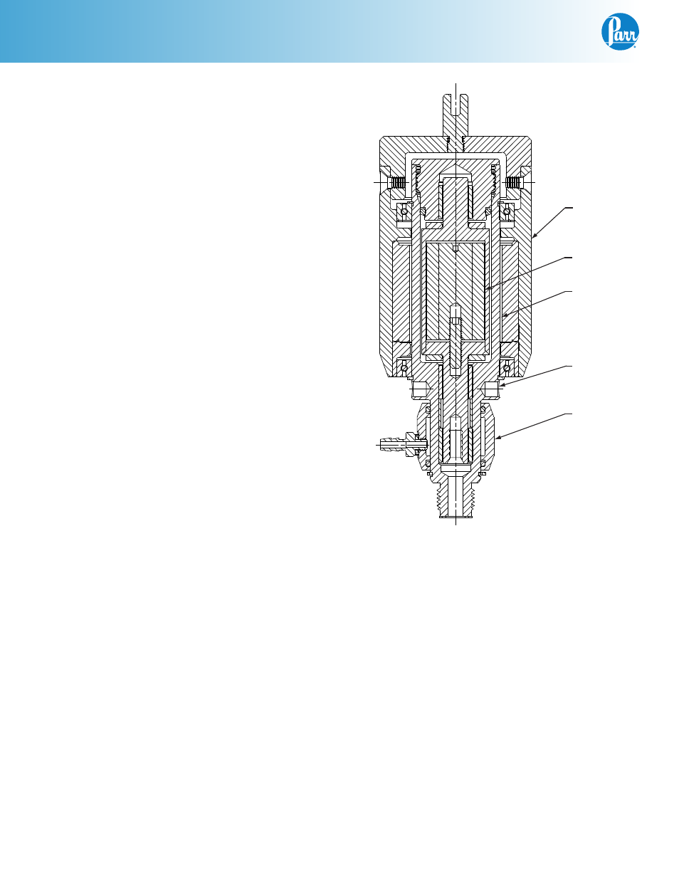
Outer Driving
Magnetic
Assembly
Inner Magnetic
Rotor
Non-Rotating
Inner Housing
Holes for
Pin Spanner
Wrench
Cooling
Sleeve
Parr Magnetic Drive