Installation – Dimplex Electric Fireplace DFG253A User Manual
Page 9
9
Installation
⑤
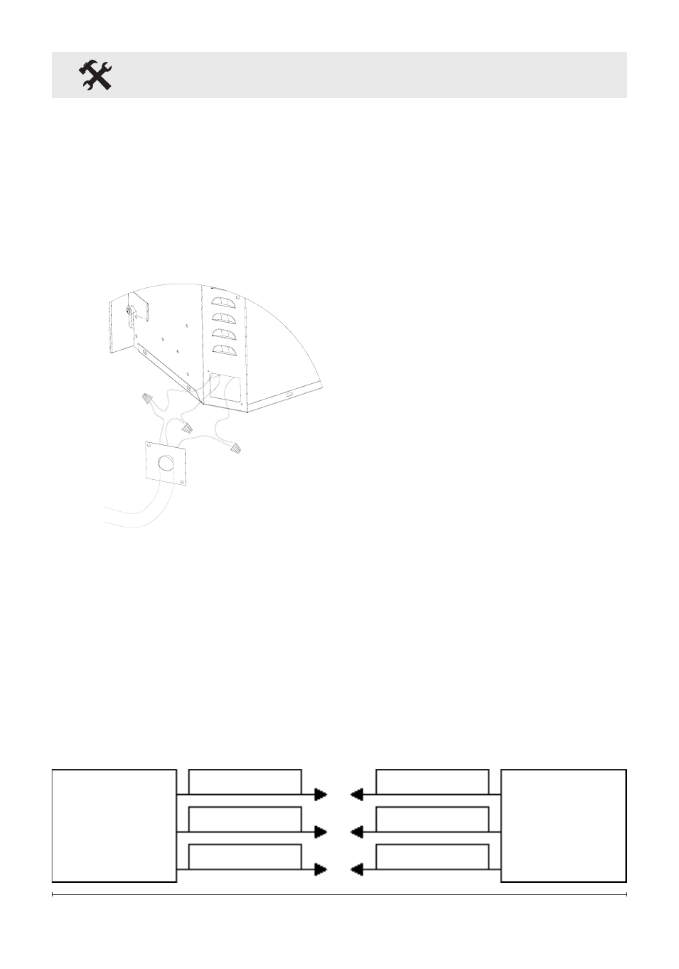
Route the power supply wire
through the knockout on supplied
alternative junction box cover
and secure with a wire clamp (not
supplied) (Figure 3).
Figure 3
⑥
Connect the black wire (live)
from the unit to the black wire
from power supply (Figure 4).
⑦
Connect the white wire
(neutral) from the unit to the white
wire from power supply (Figure 4).
⑧
Connect the green wire
(ground) from the unit to the
green wire from power supply
(Figure 4).
⑨
Place all connectors inside
the unit and secure the junction
box cover to unit. Ensure that the
cable clamp grips only the jacket
of service cable.
Figure 4
FIrEPLACE
JunCTIon
boX
120v
PoWEr
SUPPLY
(brEAKEr
PAnEL)
WhITE WIrE (n)
WhITE WIrE (n)
bLACK WIrE (L)
bLACK WIrE (L)
GrEEn WIrE (G)
GrEEn WIrE (G)