Axijet-v or kvc fan & plenum assembly installation – MK Plastics KVC IO&M User Manual
Page 7
M.K.Plastics Corp. Montréal, Québec www.mkplastics.com
7
Axijet-V or KVC Fan & Plenum Assembly Installation
Depending on the size of equipment, the Axijet-V/KVC systems may arrive in module sections due to
shipping limitations for job site assembly. Please contact the factory for further details of specific
components. Generally speaking, the module sections will consist of the following –
1. Roof curb (by M.K. Plastics or by others).
2. Plenum (may or may not have bypass dampers pre-attached, depending on the plenum size).
3. Fan housing.
4. Stack extension or stack sound attenuator (as an accessory).
5. Discharge stack/windband assembly or velocity cone (may include a transition piece depending
on fan size).
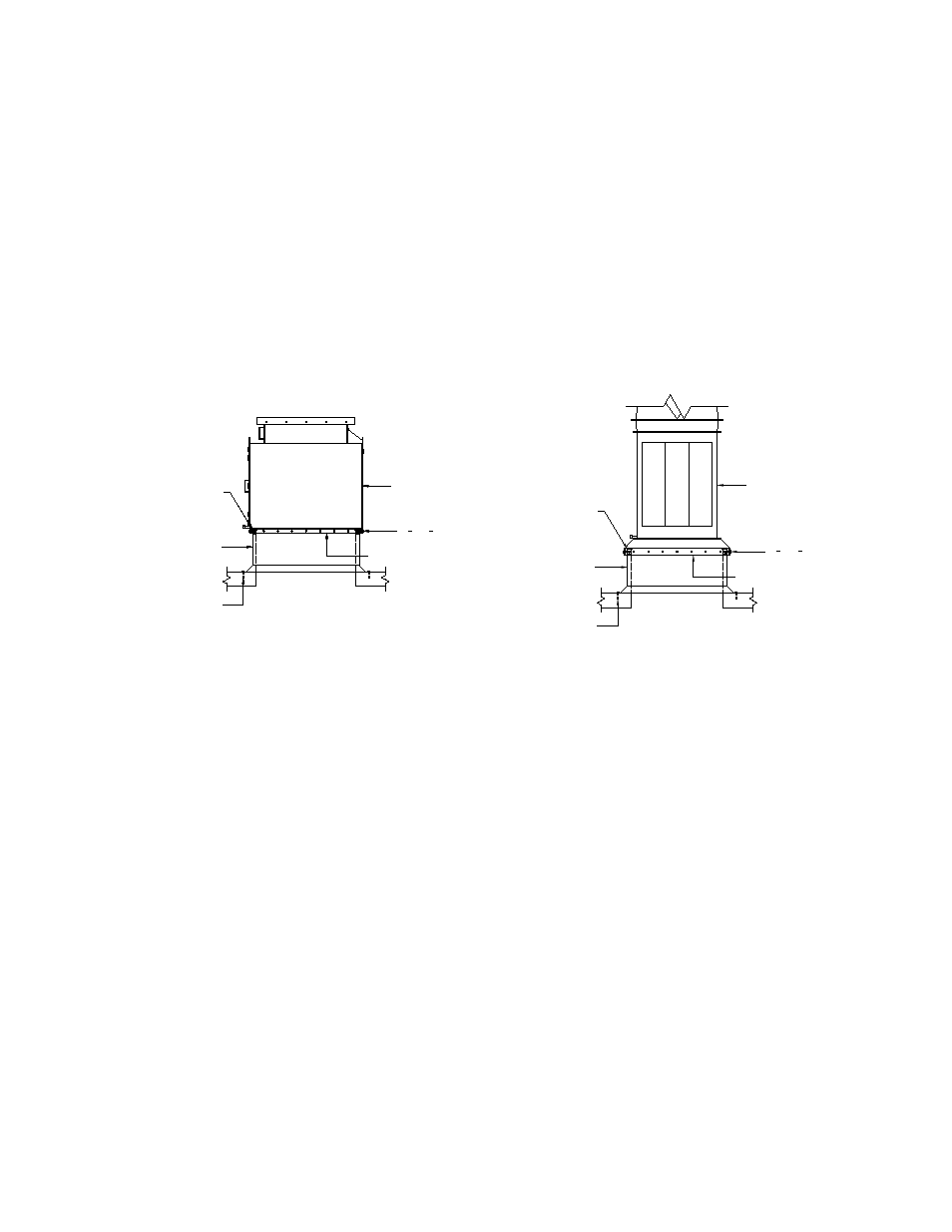
Figure-3 & Figure-4 below show a typical method on how to install an Axijet-V/KVC fan or plenum for roof
attachment. Please consult structural engineers or architects for particular attachment requirements or
methods as specific local codes may apply.
Figure-3. Plenum to Curb Attachment Figure-4. Axijet-V Fan to Curb Attachment
(KVC - Similar)
Assuming the roof curb is in place, refer to Figure-3 & Figure-4 for the following instructions –
1. Check roof curb for levelness as this could affect drainage from plenum and fan(s). Roof should
be properly and securely fastened to the roof structure, as per the project construction documents
and local building codes.
2. Secure the neoprene vibration pads to the top of the curb wood nailer strip perimeter with either
construction adhesive or countersunk self-tapping screws.
3. Lift the plenum onto the curb using a suitable hoist with chains and spreader bar (all plenums will
be supplied with lifting lugs), so that the plenum is properly centered on the curb. There should be
approximately a 1” gap all around between the inside plenum curb cap and roof curb.
4. If just the fan is being mounted, the mounting cap comes with pre-drilled holes. Drill 5/16” dia.
pilot holes through the cap holes into the curb wood nailer strip to about 2” depth.
5. If a plenum is being mounted, pre-drill through the steel curb cap 0.56” dia. holes, and then pilot
holes as described above.
6. Secure mounting or curb cap with stainless steel lag bolts. Use anti-seize gel to prevent galling or
welding of the fasteners.
ANCHOR BOLT
(OR SIMILAR)
ROOF CURB
NEOPRENE VIBRATION PAD
PLENUM CURB CAP
2-
1
2
" x Ø
1
2
" LAG BOLT
PLENUM
ANCHOR BOLT
(OR SIMILAR)
ROOF CURB
NEOPRENE VIBRATION PAD
PLENUM CURB CAP
2-
1
2
" x Ø
1
2
" LAG BOLT
PLENUM
ANCHOR BOLT
(OR SIMILAR)
ROOF CURB
NEOPRENE VIBRATION PAD
PLENUM CURB CAP
2-
1
2
" x Ø
1
2
" LAG BOLT
PLENUM
ANCHOR BOLT
(OR SIMILAR)
ROOF CURB
NEOPRENE VIBRATION PAD
PLENUM CURB CAP
2-
1
2
" x Ø
1
2
" LAG BOLT
PLENUM
ANCHOR BOLT
(OR SIMILAR)
ROOF CURB
NEOPRENE VIBRATION PAD
PLENUM CURB CAP
2-
1
2
" x Ø
1
2
" LAG BOLT
PLENUM
ROOF CURB
ANCHOR BOLT
(OR SIMILAR)
NEOPRENE VIBRATION PAD
2-
1
2
" x Ø
1
2
" LAG BOLT
FAN MOUNTING CAP
AXIJET-V