Drainage detail, Wiring installation, Figure-6. isolation damper wiring schematic – MK Plastics KVC IO&M User Manual
Page 10
M.K.Plastics Corp. Montréal, Québec www.mkplastics.com
10
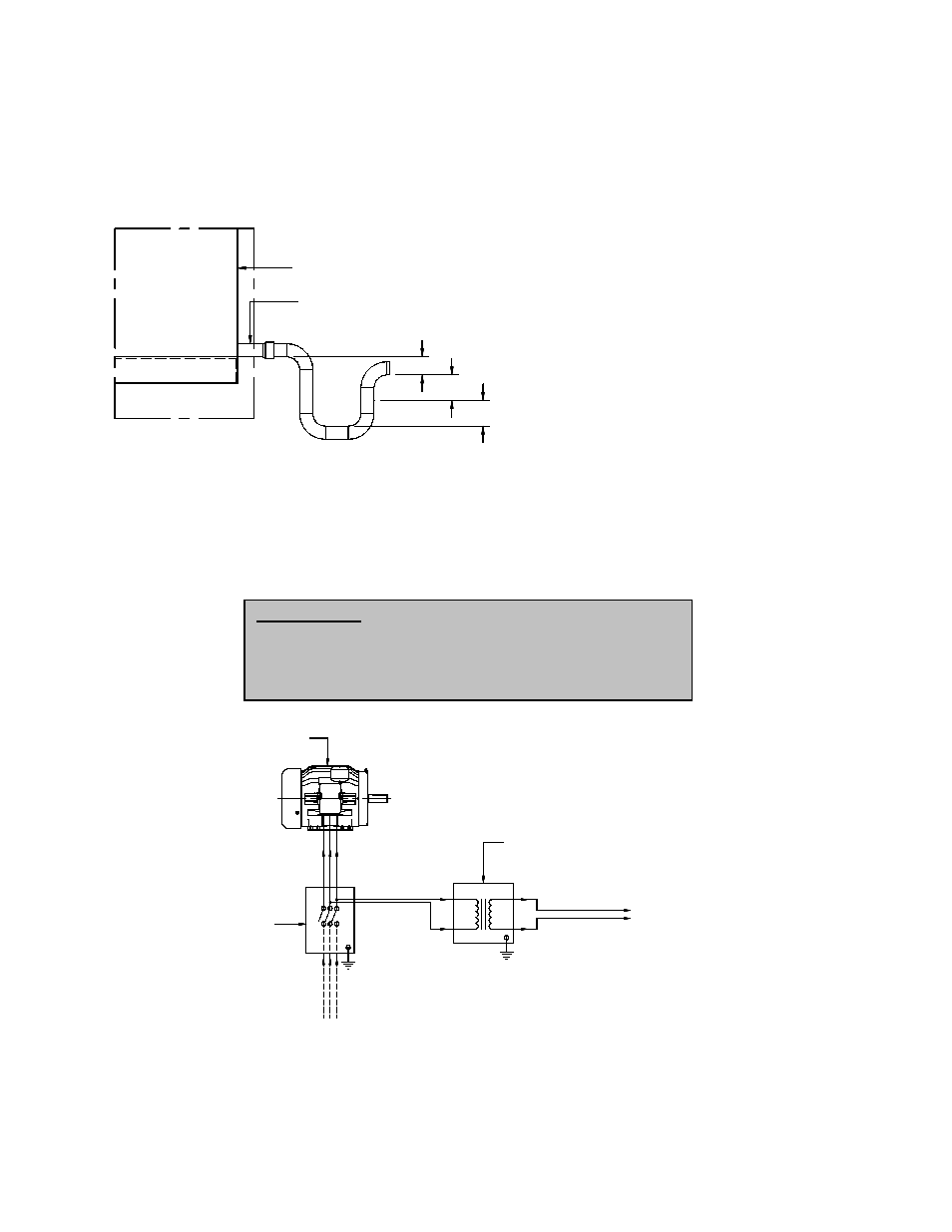
Drainage Detail
All Axijet-V/KVC fans and inlet plenums come as standard with outlet drains due to the possibility of water
or condensation that may occur. Proper disposal of water must occur by connection of drain outlet to a
drainage system (by others). Piping must have adequate pitch for proper runoff and be supported (if
needed) to prevent the possibility of sagging and overflow. The trap should be filled before start-up.
A
B
C
DRAIN COUPLING
PLENUM OR FAN HOUSING
A
B
C
DRAIN COUPLING
PLENUM OR FAN HOUSING
A
B
C
DRAIN COUPLING
PLENUM OR FAN HOUSING
A
B
C
DRAIN COUPLING
PLENUM OR FAN HOUSING
A
B
C
DRAIN COUPLING
PLENUM OR FAN HOUSING
Wiring Installation
All wiring should be in accordance with local ordinances and the National Electrical Code, NFPA 70.
Ensure the power supply (voltage, frequency, and current carrying capacity of wires) are in accordance
with the motor nameplate.
Lock off all power sources before unit is wired to power source.
DISCONNECT SWITCH
STEP-DOWN TRANSFORMER
(208/230/460/575V - 1 PHASE)
FAN MOTOR
(208/230/460/575V - 3 PHASE)
(208/230/460/575V - 3-PHASE)
LINE IN
HIGH VOLTAGE
LOW VOLTAGE
(24V OR 120V - 1 PHASE)
ISOLATION DAMPER ACTUATOR
DISCONNECT SWITCH
STEP-DOWN TRANSFORMER
(208/230/460/575V - 1 PHASE)
FAN MOTOR
(208/230/460/575V - 3 PHASE)
(208/230/460/575V - 3-PHASE)
LINE IN
HIGH VOLTAGE
LOW VOLTAGE
(24V OR 120V - 1 PHASE)
ISOLATION DAMPER ACTUATOR
DISCONNECT SWITCH
STEP-DOWN TRANSFORMER
(208/230/460/575V - 1 PHASE)
FAN MOTOR
(208/230/460/575V - 3 PHASE)
(208/230/460/575V - 3-PHASE)
LINE IN
HIGH VOLTAGE
LOW VOLTAGE
(24V OR 120V - 1 PHASE)
ISOLATION DAMPER ACTUATOR
DISCONNECT SWITCH
STEP-DOWN TRANSFORMER
(208/230/460/575V - 1 PHASE)
FAN MOTOR
(208/230/460/575V - 3 PHASE)
(208/230/460/575V - 3-PHASE)
LINE IN
HIGH VOLTAGE
LOW VOLTAGE
(24V OR 120V - 1 PHASE)
ISOLATION DAMPER ACTUATOR
DISCONNECT SWITCH
STEP-DOWN TRANSFORMER
(208/230/460/575V - 1 PHASE)
FAN MOTOR
(208/230/460/575V - 3 PHASE)
(208/230/460/575V - 3-PHASE)
LINE IN
HIGH VOLTAGE
LOW VOLTAGE
(24V OR 120V - 1 PHASE)
ISOLATION DAMPER ACTUATOR
Figure-6. Isolation Damper Wiring Schematic
A. Must be greater than system static
pressure, in inches.
B. Must be greater than1/2 of the system
static pressure, in inches.
C. 1” water seal.
Personal Safety
Disconnect switches are recommended. Place the disconnect
switch near the fan in order that the power can be swiftly cut
off in case of an emergency, and in order that maintenance
personnel are provided complete control of the power source.