Output cycling mode – Lingenfelter L460220000 Lingenfelter TBRC-001 Temperature Based Relay Controller v1.0 User Manual
Page 5
Page
Additional notes / warnings:
• Changes to the settings on the TBRC-001 must be done with the ignition off.
• The switch positions are only read when the module is powered up.
• Do NOT submerge the module in liquid or directly wash the unit with liquid of any type! The switches on the TBRC-
001 are sealed but are NOT rated for high pressure washing, use caution if power washing near the TBRC-001
module. Mount the module where it will not be exposed to constant water.
• Do NOT mount the TBRC-001 directly on top of the engine or near the exhaust manifolds due to heat concerns.
• Do NOT mount the TBRC-001 in the line of site of high temperature objects such as exhaust manifolds, turbine
housings etc. If needed, put a heat shield in between the heat source and the module to protect the plastic case.
• Do NOT install within 6” of nitrous solenoids or other devices with strong magnetic fields.
• Do NOT install near the spark plugs or the spark plug wires (or other potential strong sources of electrical noise).
• LPE recommends the use of resistor type spark plugs and RFI (radio frequency interference) and EMI
(electromagnetic interference) suppression spark plug wires on all EFI engines and any vehicle that has electronic
control modules on board (including the TBRC-001). Failure to do so may result in erratic operation of electronic
devices including the TBRC-001.
• Do NOT install a second sensor in-line with a pre-existing sensor in the system to be measured. The combined
resistance of multiple sensors will create a larger voltage drop, which will cause the TBRC-001 to inaccurately read
the temperature.
• Do NOT connect the TBRC-001 to an existing sensor being used by the vehicle’s ECM or other device.
Output Cycling Mode
If it is desired to measure the temperature inside a device that does not have provisions for a temperature sensor, the only
solution may be to put the temperature sensor in line with the device. If the temperature sensor must be installed in the
fluid lines connected to the device, the TBRC-001’s Output Cycling Mode can be used to circulate hot fluid past the sensor
(i .e. you want to cycle the pump to get the hot fluid out of the differential or transmission and past the sensor so you can
determine the temperature of the fluid in the differential or transmission). While in Output Cycling Mode, several cycle rate
and duration settings are available.
To change cycle rate and duration settings:
• Use a #1 phillips head screwdriver to remove the back cover of the unit.
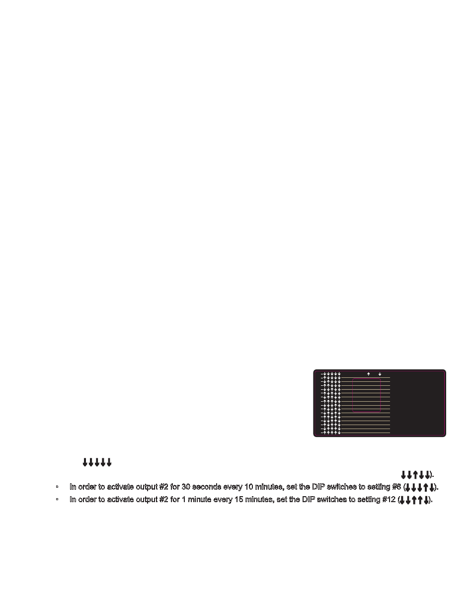
• On the inside of the unit’s back cover, there is a sticker that shows the
possible cycle rate and duration settings, as well as the correct DIP switch
configuration for each one. This graphic is shown on the right.
• Using a small flat head screwdriver, flip the correct DIP switches ON or OFF
to select the desired cycle rate and duration.
• Setting examples:
• To deactivate Output Cycling Mode, set the DIP switches to setting
#0 (↓ ↓ ↓ ↓ ↓)
• In order to activate output #2 for 15 seconds every 5 minutes, set the DIP switches to setting #4 (↓ ↓
↑ ↓ ↓).
• In order to activate output #2 for 30 seconds every 10 minutes, set the DIP switches to setting #8 (↓ ↓ ↓ ↑ ↓).
• In order to activate output #2 for 1 minute every 15 minutes, set the DIP switches to setting #12 (↓ ↓ ↑ ↑ ↓).
• Replace and secure the rear cover plate to the back of the TBRC-001.
• Power up the device to finalize the changes to the cycle rate and duration.
4.
1 2 3 4 5
ON
OFF
0
1
2
3
4
5
6
7
8
9
10
11
12
15
14
13
0 = TIMER OFF
1 MIN. DELAY, 5 SEC. ON
1 MIN. DELAY, 15 SEC. ON
5 MIN. DELAY, 5 SEC. ON
5 MIN. DELAY, 15 SEC. ON
5 MIN. DELAY, 30 SEC. ON
10 MIN. DELAY, 5 SEC. ON
10 MIN. DELAY, 15 SEC. ON
10 MIN. DELAY, 30 SEC. ON
15 MIN. DELAY, 5 SEC. ON
15 MIN. DELAY, 15 SEC. ON
15 MIN. DELAY, 30 SEC. ON
15 MIN. DELAY, 1 MIN. ON
20 MIN. DELAY, 15 SEC. ON
20 MIN. DELAY, 30 SEC. ON
20 MIN. DELAY, 1 MIN. ON
Figure 2: DIP switch settings
(This graphic can also be found under
the back cover of the TBRC-001)