Lingenfelter L460220000 Lingenfelter TBRC-001 Temperature Based Relay Controller v1.0 User Manual
Page 4
Page 3.
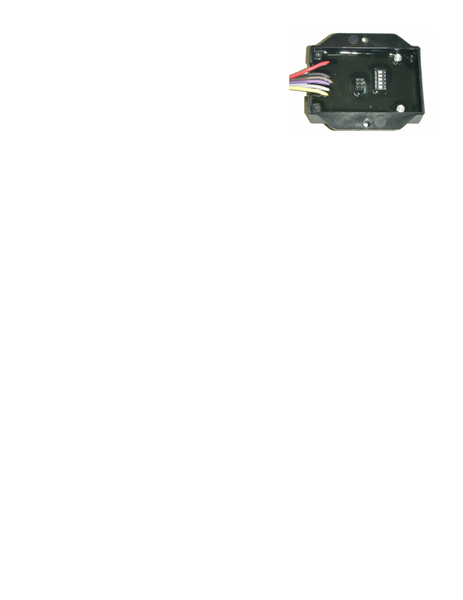
• Four (4) DIP switches for activating and controlling
Output Cycling
Mode
• Output Cycling Mode is used in applications where the
temperature sensor is not in the device that we are trying to
measure, but instead in-line with the device. See the
Output
Cycling Mode section of the instructions on page 4 for further
explanation of function and settings.
• DIP switches #1-4 are used to control this setting. DIP switch #5
is inactive and has no effect on the setting. Refer to the rear cover
graphic on page 4, which shows the available configurations.
• Output Cycling Mode is only available for relay output #2.
Operation LED Status:
• Solid RED when powered up with no temperature sensor detected or with no temperature sensor within the range of
the accepted values.
• -35°F to 350°F for IAT or ECT sensors.
• -35°F to 2500°F for EGT sensors.
• Solid GREEN when the temperature sensor is detected and within the valid temperature range, but the temperature
has not reached the user-defined activation point.
• Blinking GREEN when Relay Output #1 is active, but Relay Output #2 is inactive.
• Blinking RED when Relay Output #1 is inactive, but Relay Output #2 is active.
• Blinking GREEN+RED when both Relay Output #1 and Relay Output #2 are active.
Installation:
• Disconnect the negative battery terminal.
• Connect black wire of TBRC-001 to a suitable vehicle ground.
• Connect the red wire to a
switched and fused +12 volt DC source.
• Connect the brown wire to the ground side of the temperature sensor.
• Connect the purple wire to the sensor output signal. This signal will increase or decrease as the temperature
measured by the sensor increases, depending on the type of sensor used.
• Connect the gray wire (Relay #1) to the relay that controls your first component (such as a fan or a pump).
• Connect the yellow wire (Relay #2) to the relay that controls your second component.
• If you are using an EGT type sensor and you want to activate a relay above 1000 degrees fahrenheit, you
must connect it to this wire because relay output #2 is the only output that can be set to to above 1000 degrees
fahrenheit.
• If using Output Cycling Mode, the device to be cycled must be connected to this output.
• Secure the device using the supplied hook and loop tape or using the supplied self tapping screws.
• Set the sixteen position switch to the correct setting for the desired sensor type and hysteresis. Refer to the Table 2
on page 2 in order to select the desired setting
• If connecting to a relay through the gray wire, set the desired relay #1 ON temperature using the two (2) ten position
switches labeled “Temp1 x100” and “Temp1 x10”.
• If connecting to the relay through the yellow wire, set the desired relay #2 ON temperature using the two (2) ten
position switches labeled “Temp2 x100” and “Temp2 x10”. If the sixteen position switch (sensor type and hysteresis)
was set anywhere from ‘8’ to ‘B’, 1000 degrees fahrenheit will be added to the selected relay #2 ON temperature.