4 shunt verification, 5 operating ranges – Lamar Technologies Alpha C-25 User Manual
Page 16
4. CALIBRATION AND MAINTENANCE
ALPHA C-25 Manual V2.1.doc
Page 16
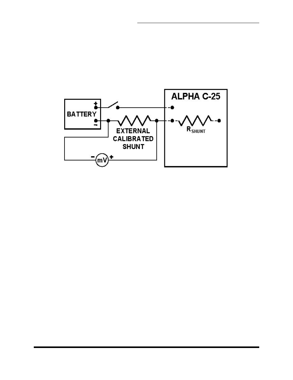
4.4 SHUNT VERIFICATION
The Alpha C-25 internal shunt is calibrated and certified by the shunt
manufacturer. The shunt is a linear resistive device consisting of a heavy brass
base and heavy manganin (copper alloy) resistance. It is not necessary to calibrate
the shunt, however the shunt could be verified with the help of an external
calibrated shunt and a millivoltmeter (see figure 4-3).
EXTERNAL CALIBRATED
MILLIVOLTMETER
Figure 4-3 Circuit diagram for shunt verification
4.5 OPERATING RANGES
The main Alpha C-25 circuit board P/N BD50PC had factory-preset trimpots for
modifying voltages settings and limits. Those trimpots are now accessible from the
front panel.
4.5.1 MODIFYING VOLTAGES FOR CONSTANT-POTENTIAL MODE
Select 12 or 24 Volt as required. Without battery connected, check end voltages of
14.3 or 28.5 volts. Trim if necessary or if different voltages are required.