2 back panel overview, 8product overview – Lab.gruppen LM 44 User Manual
Page 14
8
Product Overview
Lake LM Series Quick Start and Field Reference Guide Rev 1.2.8
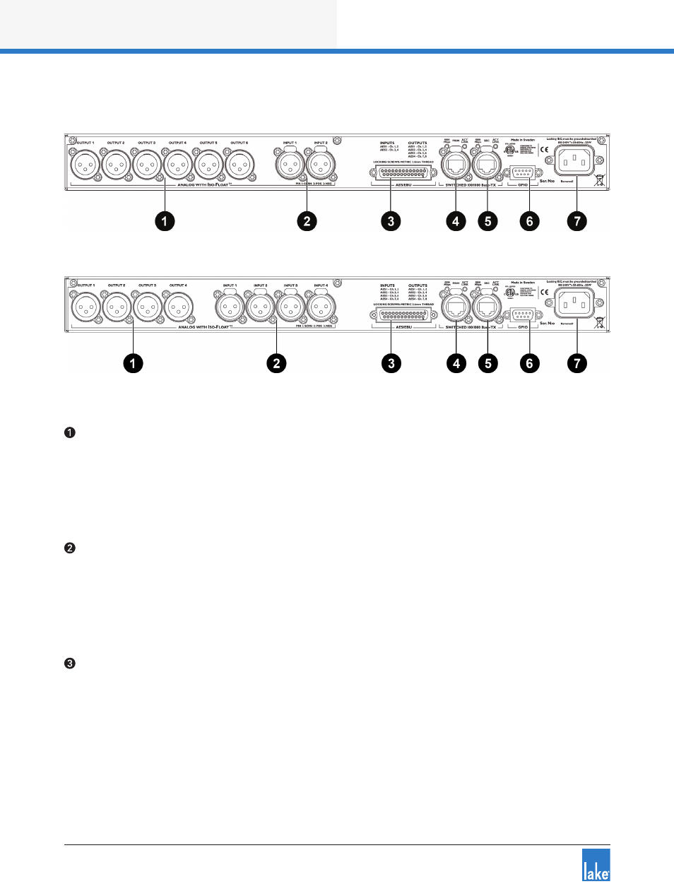
4.2 Back Panel Overview
Figure 4-2: LM 26 Back Panel Layout
Figure 4-3: LM 44 Back Panel Layout
Analog Outputs
Analog outputs are provided via standard XLR3M connections. The outputs are electronically balanced and
feature Lake Iso-Float circuitry; it is not recommended to use unbalanced connections. The output imped-
ance is 50 ohms, providing a maximum output level of +21 dBu. Please refer to section 7.1 of the LM Series
Operation Manual for further information.
Analog Inputs
Analog inputs are provided via standard XLR3F latching connectors. The inputs are electronically balanced
and feature Lake Iso-Float circuitry; it is not recommended to use unbalanced connections. The impedance
is 20 kohms (balanced), and the inputs can accept a maximum input level of +26 dBu. Please refer to section
7.1 of the LM Series Operation Manual for further information.
AES3 I/O
AES inputs and outputs are provided via a 25-pin DB25 connector. Inputs can be received on AES1 (Ch.1,2)
and AES2 (Ch.3,4) for all LM Series devices; the LM 44 also allows input from AES3 (Ch.5,6) and AES4
(Ch.7,8).
Outputs are via AES1 (Ch.1,2), AES2 (Ch.3,4), AES3 (Ch.5,6) and AES4 (Ch.7,8). Please refer to section 7.2
of the LM Series Operation Manual for further information.