Step 9, Step 10 step 11 assembly instructions (cont.) – HITEC Extra 300S User Manual
Page 7
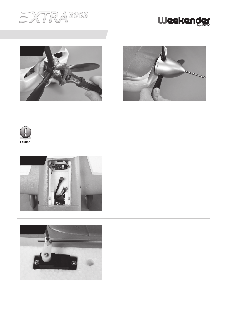
Once tightened, the distance between the cowl and spinner should be about 4 mm. If it is too close to the
cowl, damage may occur.
Step 9: Propeller Hub and Spinner assembly
Take the propeller hub and slide it through the base of the spinner assembly, then slide the propeller on the hub and
spinner base. Install the washer and nut, do not tighten. Slide this assembly onto the motor shaft and tighten the nut.
Place the spinner over the propeller and attach with the supplied screw.
SteP 9
Step 10: Receiver and battery installation
Install the receiver into the fuselage and plug in the servo
leads. The servo leads are numbered to the corresponding
receiver channel. If using a 4-channel receiver, you will need
a 6-inch Y extension for the aileron servos. Install the battery
into the cavity in the front section of the fuselage as shown
above.
Step 11: centering the control Surfaces
With the throttle stick in the lowest (off ) position, plug in the
battery to power up your model. Now set the sticks to their
neutral position and center the control surface on the airplane.
using a 1.5 mm hex head screwdriver, tighten the grub screws
against the linkages. We recommend applying a medium
strength thread locker to the screws to prevent them from
working loose.
SteP 10
SteP 11
ASSEMBLY INSTRuCTIONS (cont.)
7