Step 1, Step 3, Step 2 – HITEC Extra 300S User Manual
Page 5: Step 4 assembly instructions
tools Required for assembly
• #1 Phillips Head Screwdriver • 1.5 mm Hex Head Screwdriver • 13 mm Wrench
Section 2
Before Assembling the Extra 300S
Keep in mind when assembling and fl ying the Extra 300S, that radio control model airplanes may cause injury
or property damage when improperly fl own or mishandled. Always follow the warnings written in the instruc-
tion manual. Improper usage could lead to damage and/or failure of the electronic equipment. Be sure to read
this instruction manual in its entirety before assembling and fl ying this model.
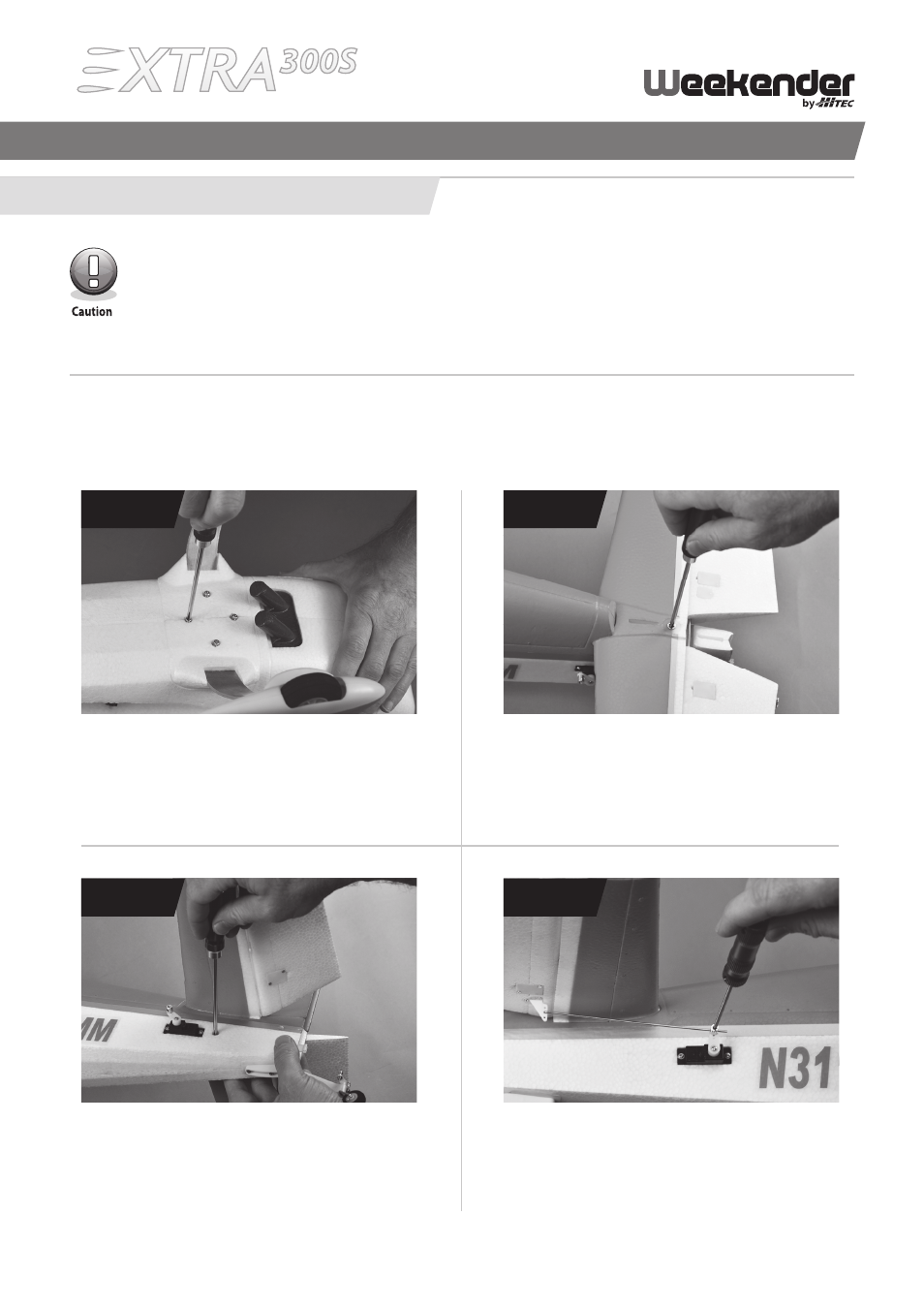
Step 1: Main landing Gear assembly
Using a #1 Phillips head screwdriver and the four
3.0 x 15 mm screws, attach the main landing gear
to the fuselage.
SteP 1
Step 3: Vertical Stabilizer assembly
Gently slide the vertical stabilizer into the two slots
cut into the fuselage and lock it into place using
the two 2.6 x 12 mm screws.
SteP 3
Step 2: Horizontal Stabilizer assembly
With the control horn facing down, slide the
horizontal stabilizer into place and attach to the
fuselage with the 4.0 x 40 mm machine screw.
SteP 2
Step 4: connecting the elevator control arm linkage
Take one of the control linkages and slide the Z bend
through the middle hole of the elevator control horn.
Slide the other end into the swivel on the servo. Tighten
the screw just enough to hold the wire in position.
SteP 4
ASSEMBLY INSTRuCTIONS
5