Step 6, Step 5, Step 7 step 8 assembly instructions (cont.) – HITEC Extra 300S User Manual
Page 6
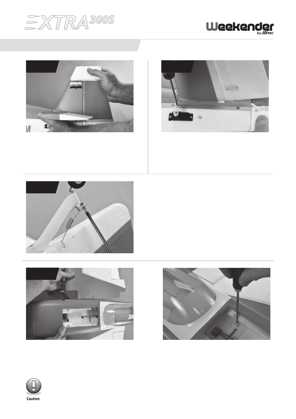
Step 6: connecting the Rudder control arm linkage
Take the remaining control linkage and slide the Z bend
through the middle hole of the rudder control horn.
Slide the other end into the swivel on the servo. Tighten
the screw just enough to hold the wire in position.
SteP 6
Step 5: attaching the Rudder
Holding the top of the vertical stabilizer, snap the
rudder into place ensuring that it moves freely on
the hinges.
Step 8: Main Wing assembly
Insert the 8 x 686 mm carbon fi ber spar tube into one of the wing halves. Slide the wing half into the fuselage making
sure to guide the servo lead through the hole in the center. Holding the installed wing halve, gently slide the other half
onto the spar tube, again making sure to guide the servo lead through the hole in the center. Insert the two 4.0 x 75 mm
machined wing retainer screws though the holes in the fuselage. Tighten until snug.
The screws should slide easily through the holes, if not, make sure the wings are fully seated and together.
Do not over tighten the screws, doing so could damage the plane.
SteP 5
Step 7: connecting the tail Wheel
Take the two springs included in the small parts package
and insert the Z bend side into the control horns on the rud-
der. Then slide the straight end into the swivel barrels. Once
both sides are installed, line up the rudder and tail wheel in
the center position. Now tighten the two screws. We rec-
ommend applying a medium strength thread locker to the
screws to prevent them from working loose.
SteP 7
SteP 8
ASSEMBLY INSTRuCTIONS (cont.)
6