Hanna Instruments BL 7916 User Manual
Page 4
7
6
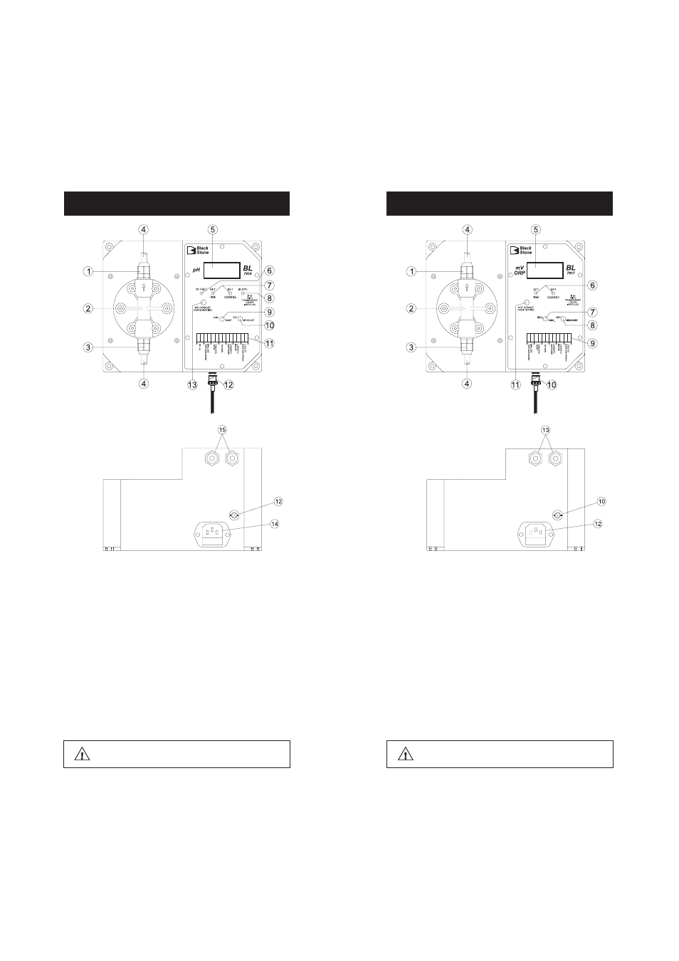
FUNCTIONAL DESCRIPTION BL 7917
Unplug the instrument from the power supply before
replacing the fuse or making any electrical connections.
1. Discharge Valve Assembly
2. Pump head
3. Suction Valve Assembly
4. Hose
5. Liquid Crystal Display
6. Setpoint Adjustment Trimmers (FINE and COARSE)
7. Reduction/Oxidation Selection Switch
8. Operating Mode Selection Switch (SET or MEASURE)
9. Terminal Connections
10. BNC Connector for ORP electrode
11. Overheating LED
12. Power Socket and Fuse Holder
13. Cable Glands
FUNCTIONAL DESCRIPTION BL 7916
1. Discharge Valve Assembly
2. Pump head
3. Suction Valve Assembly
4. Hose
5. Liquid Crystal Display
6. Offset Calibration Trimmer
7. Setpoint Adjustment Trimmers (FINE and COARSE)
8. Slope Calibration Trimmer
9. Acid/Base Selection Switch
10. Display Mode Selection Switch (SET or MEASURE)
11. Terminal Connections
12. BNC Connector for pH electrode
13. Overheating LED
14. Power Socket and Fuse Holder
15. Cable Glands
Unplug the instrument from the power supply before
replacing the fuse or making any electrical connections.