Functional diagram hi 9934, Front panel – Hanna Instruments HI 9931 User Manual
Page 9
9
FUNCTIONAL DIAGRAM HI 9934
FUNCTIONAL DIAGRAM HI 9934
FUNCTIONAL DIAGRAM HI 9934
FUNCTIONAL DIAGRAM HI 9934
FUNCTIONAL DIAGRAM HI 9934
TDS
0
200
400
ALARM
mA OUTPUT
4/20
0/20
ppm
TIMER
MINUTES
FINE
SLOPE
CAL
COARSE
PROPORTIONAL SETTINGS
AUTO
MANUAL
SET
READ
FERT.
SET POINT
1
10
2.5
5
7.5
FEED
ALARM
LINE
SET TDS
ZERO
CAL
1
2
3
4
5
6
7
8
9
10
11
12
13
14
15
16
17
18
19
20
0
SECONDS
ppm
400
0
90
45
HI 9934
200
ppm
TDS
ALARM
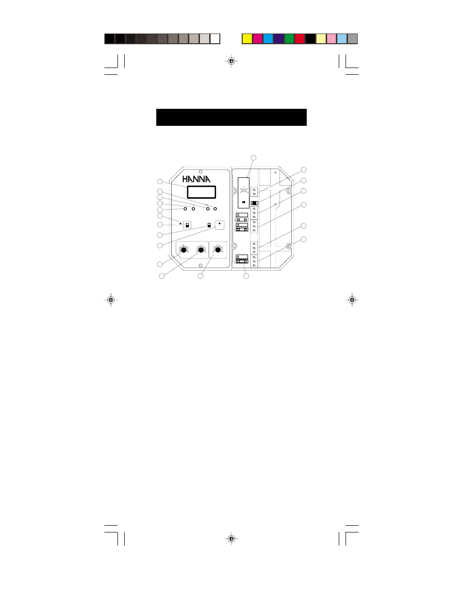
FRONT PANEL
Left panel
1. Liquid Crystal Display
2. Slope calibration trimmer
3. Fine setpoint trimmer
4. Coarse setpoint trimmer
5. Zero calibration trimmer
6. Alarm LED warning signal
7. Alarm disable switch
8. READ for actual measurement and SET for setpoint
adjustment
9. Dosing LED signal
10. Proportional TDS band setting
11. Proportional time cycle setting
12. Overdosage timer
Right panel
13. TDS alarm setting from 0 to 400 ppm (mg/L)
14. Recorder output contacts
15. 0 to 20 or 4 to 20 mA output selector
16. Triple contact alarm in a Normally Closed (NC) or a Normally