Hanna Instruments HI 4014 User Manual
Page 6
10
11
9. Tighten the electrode cap onto the body and fill elec-
trode body until fill solution volume is just below fill
hole.
10. Position electrode in a Hanna HI 76404 electrode
holder (or equivalent) and connect BNC connector to
meter.
IX.
IX.
IX.
IX.
IX. Quick Check of Electrode Slope
Quick Check of Electrode Slope
Quick Check of Electrode Slope
Quick Check of Electrode Slope
Quick Check of Electrode Slope
•
Connect electrode(s) to pH/mV/ISE meter.
•
Place meter in mV mode.
•
Place 100 mL of deionized water into a beaker with
stir bar.
•
Place reference and measuring half-cell or combina-
tion electrode into prepared sample.
•
Add 1 mL of a standard to beaker. Record the mV
value when stable.
•
Add an additional 10 mL of standard to the solution.
Record the mV when reading has stabilized. This
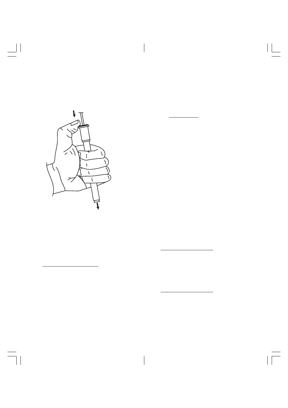
7.
upper cap with your thumb. This permits the fill solu-
tion to drain out of the body.
8.
HI
41
14
POT
ASSIUM
COMBINA
TION
value should be more than the previous value noted
(more positive).
•
Determine the difference between the two mV values.
An acceptable value for this slope is
56 ± 4 mV at typical room temperatures
(20-25
°C).
X.
X.
X.
X.
X. Corrective Action
Corrective Action
Corrective Action
Corrective Action
Corrective Action
•
Verify module has been screwed into sensor handle or
inner stem.
•
Verify seal has been removed from ceramic junction
(HI 4114) or HI 5315 reference electrode.
•
Verify electrodes are connected properly to meter and
meter is powered.
•
Verify dilute standards are freshly made and stored.
Remake solutions if appropriate. Store in plastic
bottles.
•
If the reading is unstable, shake sensor down (see
Section VII).
•
If the sensor slope just misses the suggested slope
window, soaking the sensor in a standard may solve
the problem.
•
If the membrane is damaged, the response becomes
extremely sluggish, or the slope of the electrode has
decreased significantly, and procedures above have
not helped, the modules should be replaced.
Module replacement for HI 4014
1. Dry off module and sensor handle.
2. Unscrew sensing module and replace with a new one.
(HI 4014-51).
3. Soak new assembled module in potassium solution
to condition it before calibration.
Module replacement for HI 4114
1. Drain the fill solution by depressing cap. Rinse elec-
trode with distilled or deionized water. Drain.
2.
3. Move spring and outer body down cable also.
4. Dry off inner stem and module with a soft tissue.
Holding the body of the electrode gently press the
Release the cap and verify electrode returns to its
original position. (You may need to gently assist for
this to occur).
Unscrew upper cap and slide down cable toward
connector.