4 installation, 5 electrical connection – Glow-worm Ultimate 40CF User Manual
Page 10
10
221785B
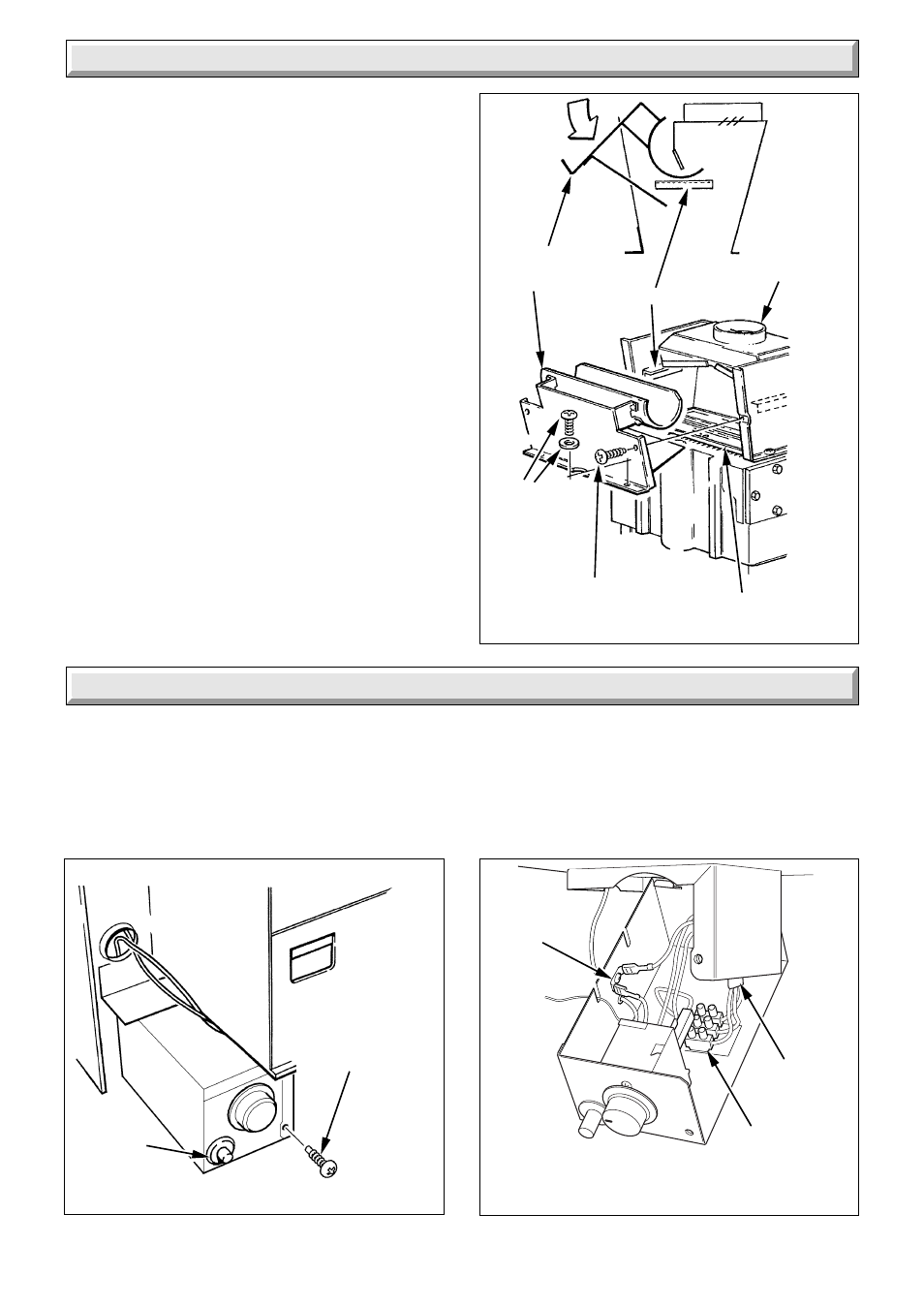
5.1 Control Box Removal
Remove the electrical control box securing screw, see diagram
5.1. Pull the control box down at the front and pull forwards to
release from hook at rear, see diagram 5.2.
Diagram 5.1
Diagram 5.2
MAINS CABLE
CONNECTION
PIEZO UNIT
8047
ELECTRICAL
CONTROL BOX
SECURING
SCREW (1)
PIEZO
UNIT
EARTH
TERMINAL
STRIP
8038
Diagram 4.6
FLUE CLEANING DOOR
2122
FLUE
CLEANING
DOOR
GUIDE (2)
FLUE
SOCKET
SECURING
SCREW
WASHER (2)
FLUEWAY BAFFLE
SELF-TAPPING
SECURING SCREW (2)
4 Installation
4.4 Water Circulation System
Complete the water connections to the boiler pipework, using
compression fittings.
Fill, vent and cold flush the system as recommended in the
current issue of BS6798.
Visually check for and put right any water leaks.
4.5 Gas Connection
Make the gas connection to the flanged Rc
1
/
2
gas service cock.
4.6 Flue
Install the flue pipework and seal to the flue socket in accordance
with normal practice.
5 Electrical Connection
5.2 Cable Connection
Thread the mains cable through the clamp at the rear of the
control box and connect to the terminal strip, see diagram 5.2.
The earth conductor must be made of a greater length so that
if the cable is strained the earth conductor is the last to become
disconnected.
MAINS
CABLE