5 boiler installation – Glow-worm Micron 60FF User Manual
Page 16
16
2000225228C
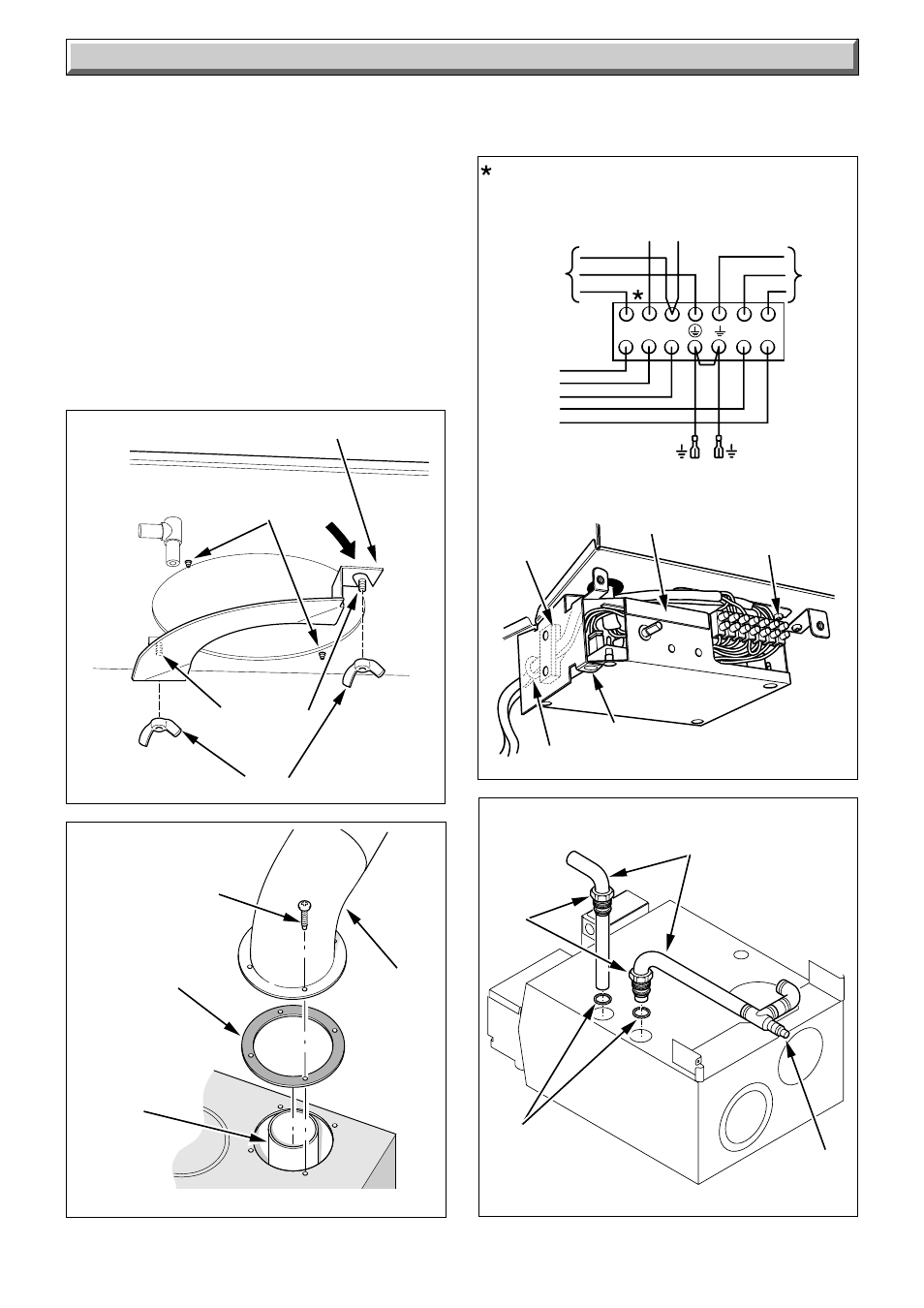
MAINS
NOTE : A SWITCH LIVE (Ls) SHOULD BE CONNECTED
FROM AN EXTERNAL CONTROL.
IF NO EXTERNAL CONTROL IS AVAILABLE INSERT A
LINK BETWEEN Lp & Ls.
SUPPLY
230V ~ 50Hz
L
P
L
S
N
P
L
P
N
b
g/y
br
BLOCK
CONNECTOR
TO
PUMP
br
bl
bl
b
b
y
p
Diagram 5.10
5 Boiler Installation
SECURING
SCREW
12385
CONTROL
BOX
When making connections, make sure that the earth conductor
is made of a greater length than the current carrying conductors,
so that if the cable is strained the earth conductor would be the
last to become disconnected.
5.8 Pump Connection
Route pump cable as mains, see diagram 5.10.
5.9 Testing
Checks to ensure electrical safety must be carried out by a
Competent person.
After installation of the system, preliminary electrical system
checks as below should be carried out:
1. Test insulation resistance to earth.
2. Test earth continuity and short circuit of all cables.
3. Test the polarity of the mains.
Diagram 5.9
TOP
TURRET
6793
GASKET
SCREWS
(4)
TOP TURRET
FLUE OUTLET
FLUE
DUCT
EXTENSION
HINGE PIN
CABLE
CLAMP
GROMMET
The installer is requested to advise and give guidance to the
user of the controls scheme used with the boiler.
Fit the casing.
Diagram 5.11
7333
TAIL PIPE
TUBING
NUT
AIR VENT
RETURN
FLOW
RUBBER
WASHER
Diagram 5.8
WING NUT
AIR DEFLECTOR
7665
TAPTITE
SCREWS
(2)
SELF-TAP
SCREWS (2)