10 replacement of parts – Glow-worm 56/3e Back Boiler User Manual
Page 29
29
221725B
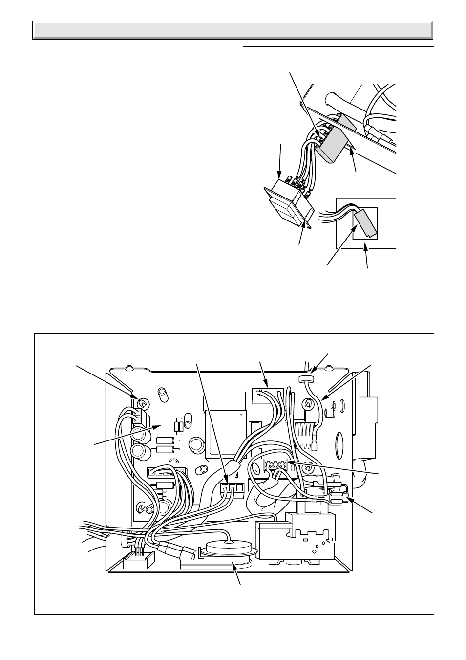
Diagram 10.5
6199
10 Replacement of Parts
LOCKOUT
RESET
BUTTON
MULTI PIN
CONNECTOR
RELEASE
TABS
Diagram 10.6
7182
IGNITION
LEAD
MULTI PIN
CONNECTOR (4)
MAINS
TERMINAL
STRIP
CONTROL
BOARD
(PCB)
SUPPORT (4)
FRONT VIEW
SHOWING HOLE IN
FRONT OF
CONTROL BOX
HOLE IN FRONT
OF CONTROL BOX
MULTI PIN
CONNECTOR
EARTH
LEAD
GROMMET
OVERHEAT CUT-OFF DEVICE
(SEALED SYSTEMS ONLY)
Lead plug
replaces
orange link
Release the wires from the mains terminal strip.
Carefully pull the board from its supports.
When refitting refer to the wiring diagram 5.6.
10.11 Over Heat Cut-off Device (Sealed
systems only)
Remove the combustion chamber extension, see diagram 4.5.
Remove the control box refer to the relevant parts of Section
8.3.
Remove the over heat phial and unclip the capillary tube, see
diagram 5.4.
Remove the locknut, see diagram 10.7.
Remove the over heat electrical connections, see diagram
10.7.
Remove the over heat cutoff device and capillary, see diagram
10.7.
When refitting, the capillary should pass through the cut-out slot
in the control box, see diagram 10.3.
When refitting refer to the wiring diagram 5.6.
The capillary tube must not touch any part of the back boiler that
becomes hot, re-clip the capillary tube and push the phial into
the pocket.
10.12 Solenoids
Refer to diagram 10.8.
Remove the gas control plug at the gas control valve.
Remove the solenoid securing screw.
Remove the solenoids.