10 replacement of parts – Glow-worm 56/3e Back Boiler User Manual
Page 27
27
221725B
10 Replacement of Parts
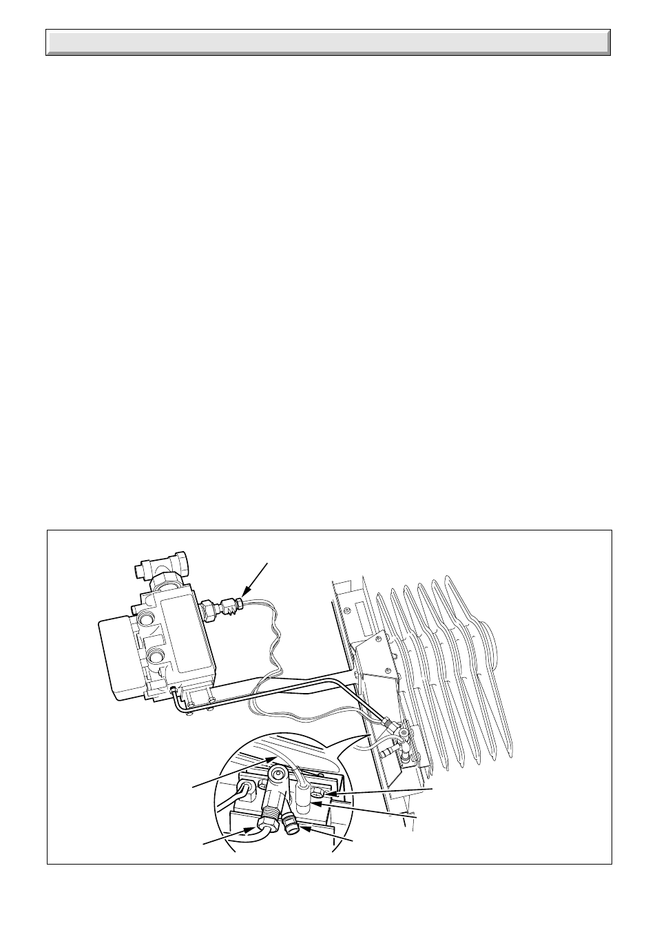
Diagram 10.1
6887
IGNITION LEAD
THERMOCOUPLE NUT
PILOT PIPE NUT
FLUE BLOCKAGE
SAFETY DEVICE
SECURING
SCREW (2)
SILICONE SLEEVE
Notes.
a) Replacement of parts must be carried out by a
competent person.
b) Unless stated otherwise all parts are replaced in the
reverse order to that of removal.
c) After replacing any gas carrying parts always test for
gas soundness using a suitable leak detection fluid.
Also carry out functional check of controls.
d) Refer to the Gas Fire Installation Instructions for
details of the removal of the fire front.
e) Isolate the electrical supply to the back boiler.
f) Refer to diagram 6.1 to identify the back boiler
controls.
Turn the thermostat control knob clockwise to “0”, “Off” position.
Turn the appliance gas service cock to the “Off” position, see
diagram 4.12.
10.1 Sensing Tube Assembly.
Refer to Section 8.2.
10.2 Flue Blockage Safety Device
Follow the instructions in Section 8.2 and 8.3 to remove the
sensing tube assembly and controls assembly and burner.
Refer to diagram 10.1.
Remove the ignition lead from the electrode.
Disconnect the thermocouple nut.
Disconnect the pilot pipe nut.
Remove the safety device securing screws.
Remove the safety device.
10.3 Thermocouple
Proceed as in Section 10.2.
10.4 Electrode
Proceed as in Section 10.2.
10.5 Ignition Lead
Remove the combustion chamber extension, see diagram 4.5.
Remove the control box refer to the relevant parts of Section
8.3.
Remove the lead from the electrode.
Remove the lead from the control board (PCB).
When replacing make sure the lead passes through the grommet
in the rear of the control box and the protective silicone sleeve
is replaced.
10.6 Injector - Main Burner
Follow the instructions in Section 8.4 to remove the burner.
Replace the main injector, Ensure you fit the new copper
washer, see diagram 8.7.
10.7 Gas Control Valve
Remove the combustion chamber extension, see diagram 4.5.
Refer to diagram 10.2.
Disconnect the union nut at the at the gas service cock, support
with a spanner, refer to diagram 4.12.
Disconnect the gas control electrical plug.
Disconnect the thermocouple nut at the gas control valve and
ease out.
Disconnect interrupter electrical connections.
Disconnect the pilot tubing nut at the gas valve.
Undo the securing screws to separate the gas control valve
from the supply pipe flange and gas manifold.
Pull the gas control valve forward releasing it from the retaining
pin, see diagram 8.4.