10 replacement of parts – Glow-worm 56/3e Back Boiler User Manual
Page 28
28
221725B
10 Replacement of Parts
6882
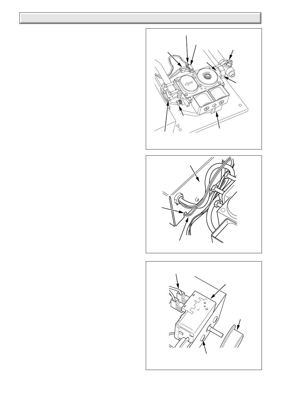
Diagram 10.4
7157
Diagram 10.2
THERMOCOUPLE NUT
PILOT
TUBING
NUT
CONTROL
KNOB
ELECTRICAL
CONNECTION (2)
CONTROL
THERMOSTAT
SECURING
SCREWS
INTERRUPTER
SECURING
SCREWS (4)
ELECTRICAL
CONNECTIONS
GAS CONTROL
ELECTRICAL PLUG
7178
Diagram 10.3
SLOT
CAPILLARY
CONTROL BOX
UNION
NUT
LINER
GAS
SERVICE
COCK
Remove the interrupter.
Remove the liner and union nut.
Transfer the interrupter to the replacement gas control valve.
Transfer the liner and union nut using a small amount of
approved jointing compound on the external threads only to the
replacement gas control valve.
Fit the new 'O' ring seal supplied with new gas control valve.
Note. When replacing the thermocouple only tighten the nut a
quarter turn beyond finger tight.
Should the solenoids require replacing, refer to Section 10.12.
10.8 Burner
Follow the relevant instructions in Section 8.3 and 8.4 to remove
the burner.
Transfer the flue blockage safety device to the new burner, see
diagram 10.1.
10.9 Control Thermostat
Remove the combustion chamber extension, see diagram 4.5.
Remove the control box refer to the relevant parts of Section
8.3.
Remove the control thermostat phial and unclip the capillary
tube, see diagram 5.4.
Remove the control knob, see diagram 10.4.
Remove the two electrical connections from the control
thermostat, see diagram 10.4.
Remove the two securing screws and remove the control
thermostat and capillary, see diagram 10.4.
When refitting, the capillary should pass through the cut-out slot
in the control box, see diagram 10.3.
The capillary tube must not touch any part of the back boiler that
becomes hot, re-clip the capillary tube and push the phial into
the pocket.
NOTE: When fitting the phial use heat sink compound and
ensure the phial is fully inserted into the phial pocket.
When refitting refer to diagram 5.4.
10.9 Lockout Reset Button
Remove the combustion chamber extension, see diagram 4.5.
Remove the control box refer to the relevant parts of Section
8.3.
Remove the lockout reset button multi pin connector from the
control board, release the tabs to remove the lockout reset
button, see diagram 10.5.
NOTE: Turn the multi pin connector and carefully ease through
the hole in the front of the control box as shown in diagram 10.5.
When refitting refer to the wiring diagram 5.6.
10.10 Control Board (PCB)
Remove the combustion chamber extension, see diagram 4.5.
Remove the control box refer to the relevant parts of Section
8.3.
Refer to diagram 10.6.
Disconnect the ignition lead.
Disconnect the electrical connections from the control thermostat.
Disconnect the four multi pin connector .
Disconnect the earth lead.