5 electrical wiring – Glow-worm BBU 45/4 User Manual
Page 16
16
2000225023C
Remove the boiler user control and its long connecting lead
from the control box, see diagrams 5.8 and 10.4.
Remove the long connecting lead and bracket from boiler user
control, first unscrewing cable grip to remove support bracket
and then unplug lead. Discard support bracket and long lead,
see diagram 5.6.
Plug the short connecting lead (supplied in the fire front fittings
pack) into the boiler user control
Slide the boiler user control into position on the control box front,
making sure that it fits into the groove in the control box, and
connect the lead plug on to P.C.B., see diagrams 5.8 and 10.4.
Refit the control box lid ensuring the boiler user control locates
into the slot on the underside of the lid, see diagram 5.7.
Refit the control box securing screws.
5.5 Testing - Electrical
Checks to ensure electrical safety must be carried out by a
competent person.
After installation of the system, preliminary electrical system
checks as below should be carried out,
1. Test insulation resistance to earth of mains cable.
2. Test the earth continuity and short circuit of all cables.
3. Test the polarity of the mains.
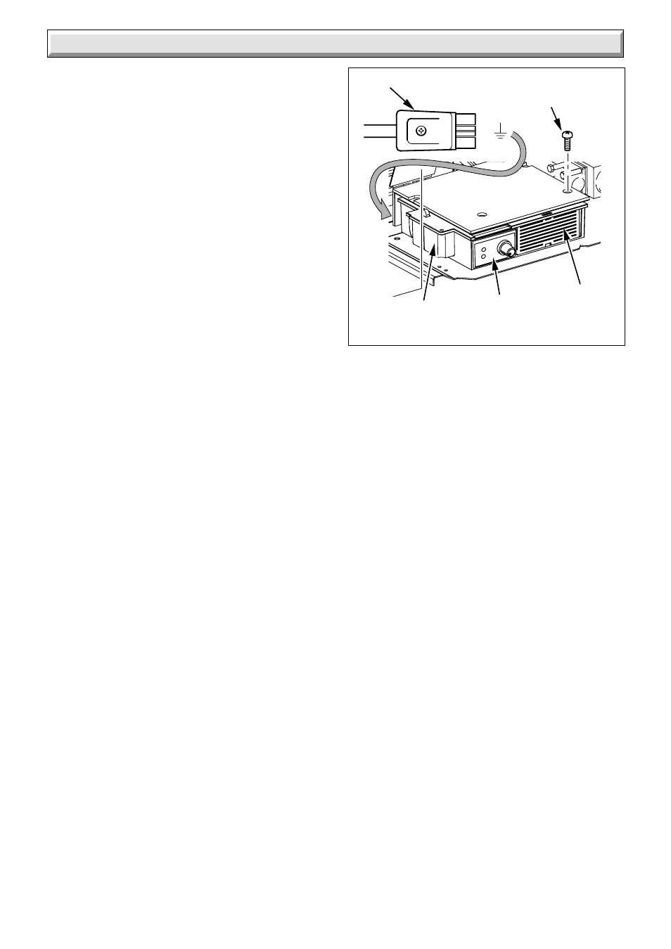
4. With the mains supply off. Plug the mains supply plug into the
control box socket, see diagram 5.5.
5.6 Overheat Cut-off Device
(sealed systems only)
A kit No. 2000463000 is available with Fitting Instructions.
5 Electrical Wiring
Diagram 5.7
9395
MAINS SUPPLY
PLUG
CONTROL BOX
SOCKET
CONTROL
BOX
L
E
N
SECURING
SCREWS
(4)
BOILER USER
CONTROL