FeiYu Tech FY-30A User Manual
Page 3
GuiLin FeiYu Electronic Technology Co., Ltd
http://www.feiyudz.cn
E-mail:
GuiLin FeiYu Electronic Technology Co., Ltd
page 3
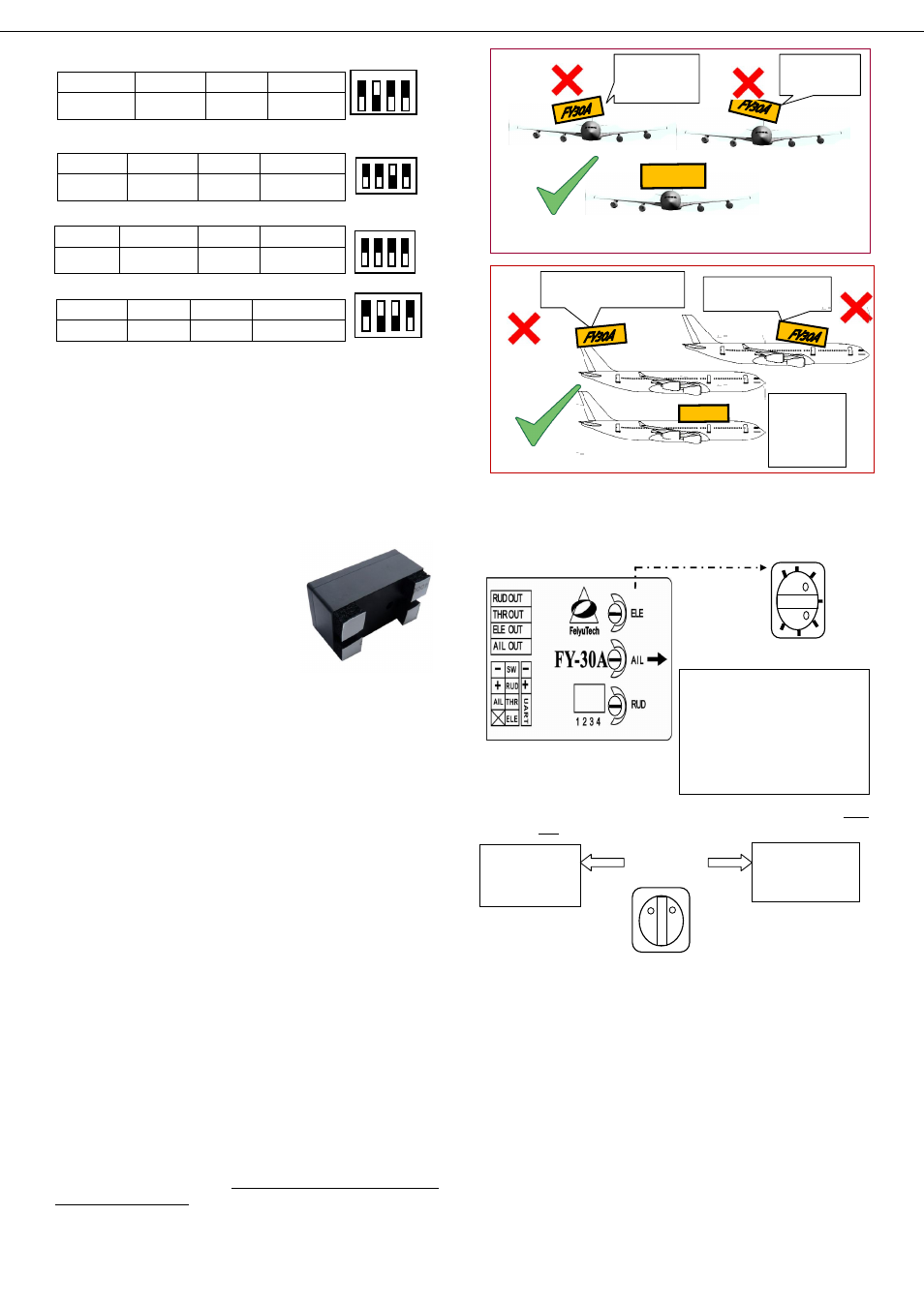
c) FY30A connection for V tail aircraft with Aileron:
AIL OUT
ELE OUT
THR OUT
RUD OUT
Aileron servo
Differential
Servo 1
ESC
Differential
Servo 2
d) FY30A connection for V tail aircraft without ailerons:
AIL OUT
ELE OUT
THR OUT
RUD OUT
Differential
Servo 1
Differential
Servo 2
ESC
NULL
e) FY30A connection for traditional layout aircraft with no Aileron:
AIL OUT
ELE OUT
THR OUT
RUD OUT
Rudder
servo
Elevator servo
ESC
Null
f)Camera Gimbal Stabilization;
AIL OUT
ELE OUT
THR OUT
RUD OUT
Roll Servo
Tilt Servo
NULL
Pan Servo
* Note: The camera gimbal Roll, Tilt and Pan servos will counter any
linear movement of the camera mount. You can move the camera at any
angle and upon releasing the stick, the FY30A will maintain
stabilization at that angle.
FY-30A and Vibration Control
a)
FY-30A is vibration-sensitive. To optimize its stabilization
capability, vibrations reaching the unit must be kept at a minimum.
b)
When installing this flight stabilizer, we highly recommend
that you install it with the supplied vibration absorbing pads (dampers).
c)
The algorithm in the FY-30A compensates for normal levels
of flight vibration. However, if the vibration
experienced by the unit exceeds the
acceptable level, it will not work normally
or may even stop working altogether.
d)
To keep vibration at a minimum,
install the FY-30A away from the engine or
any other vibration sources.
e)
The included shock-absorbing
pads will meet the damping requirements
for electric powered aircrafts and most gas / nitro planes.
How to check installation requirements to meet the shock
Even with the shock absorbing mount, your aircraft installation may not
meet the damping requirements of the FSS. To confirm correct vibration
damping, please follow this procedure:
A.
After connecting all wires between the Receiver, FY-30A and
Servos, install the unit as recommended (ensure correct orientation).
B.
Run the plane engine or motor at different throttle levels. DO
NOT TAKE OFF.
C.
Move the throttle level to different positions and maintain it
for 20 seconds at each position.
D.
At each throttle position, observe the state of the red LED
light. If it stays OFF, that means your vibration level is acceptable.
E.
If instead the red LED lights up brightly and stays ON solid,
then the vibration dampening is not enough. You will need reduce the
level of vibration on your aircraft, add additional dampening support or
change the installation location.
F.Vibration Security: An updated feature of the FY-30A is
emergency stabilization in case of sudden high vibration during flight.
In such a situation, the FY-30A will automatically activate the highest
level of stabilization and therefore withstand vibration better. This
feature should allow you to safely return the plane for an emergency
landing.
Fy-30a Installation: Orientation, Position & Level
i. The FY-30A has an arrow printed on the top of it. Orient the
arrow towards the front of the craft (i.e. direction of flight).
ii. When installing, please keep the FY-30A horizontal and as close
as possible to the "
Centre of gravity
" (C o G) of the aircraft.
iii. The benchmark for the FY-30A is its horizontal position.
Therefore, physically adjust the FY-30A into horizontal position when
the plane is in level flight:
iv. If there is deviation between the FY-30A horizontal position and
the plane’s level flight, it may cause the neutral value to be different
between the Manual Mode and the auto Stabilized Mode. See next topic.
Adjustment Dials for ELE, AIL and RUD
1. There are 3 adjustment dials on the FY30A. Each dial controls both
gyro gain and servo direction during auto stabilization.
2. Gyro Gain: The further away from Centre (12 O’clock) the higher the
Gyro gain (sensitivity). Too low gain result is poor auto stabilization,
too high gain will cause oscillations of the aircraft. You need to adjust
the gain setting based on the requirement of your aircraft.
3. Servo Direction: The dials also control the direction of your servo
movement. Turning it clockwise or counter clockwise from 12 O’clock
will change the direction of your servos during tilting, roll and yaw
movement.
FY-30A Pre-flight Set Up
Install FY30A as recommended in this manual, then proceed with
pre-flight setup:
1. Confirm that the control surfaces do not move when the aircraft is
tilted and the FY30A is in Mode 1 (Manual mode).
2.
Activate Mode 3 (Auto stabilize mode) and observe the movement
direction of Aileron, Elevator and Rudder. The direction should be as
shown below. If it does not, turn the appropriate dial to the opposite side
2
4
3
1
ON
OFF
2
ON
1
3 4
OFF
1 2 3 4
OFF
ON
ON
OF
F
1 2 3 4
Plane roll remains level when in Auto Stabilization Mode
Plane will roll to
the right when in
Stabilized Mode
Plane will roll to
the left when in
Stabilized Mode
FY-30A
Plane nose will pitch down when
in Auto Stabilization Mode.
Plane nose pitches up when
in Auto Stabilization Mode.
Plane pitch
remains level
when in Auto
Stabilization
Mode
FY-30A
Max Gyro Gain
Max Gyro Gain
12 O’clock
Min Gyro Gain
Servo direction
change during
auto stabilization
Servo direction
change during
auto stabilization
The 3 dials control both gain and
servo direction.
The gyro gain is lowest when the
knob in the middle. i.e. The further
away from center, the higher the
gyro gain.
Turning the knob left or right
off-center will change servo direction
for stabilization.
+100 Max
-100 Max
0 Min