FeiYu Tech FY-30A User Manual
Page 2
GuiLin FeiYu Electronic Technology Co., Ltd
http://www.feiyudz.cn
E-mail:
GuiLin FeiYu Electronic Technology Co., Ltd
page 2
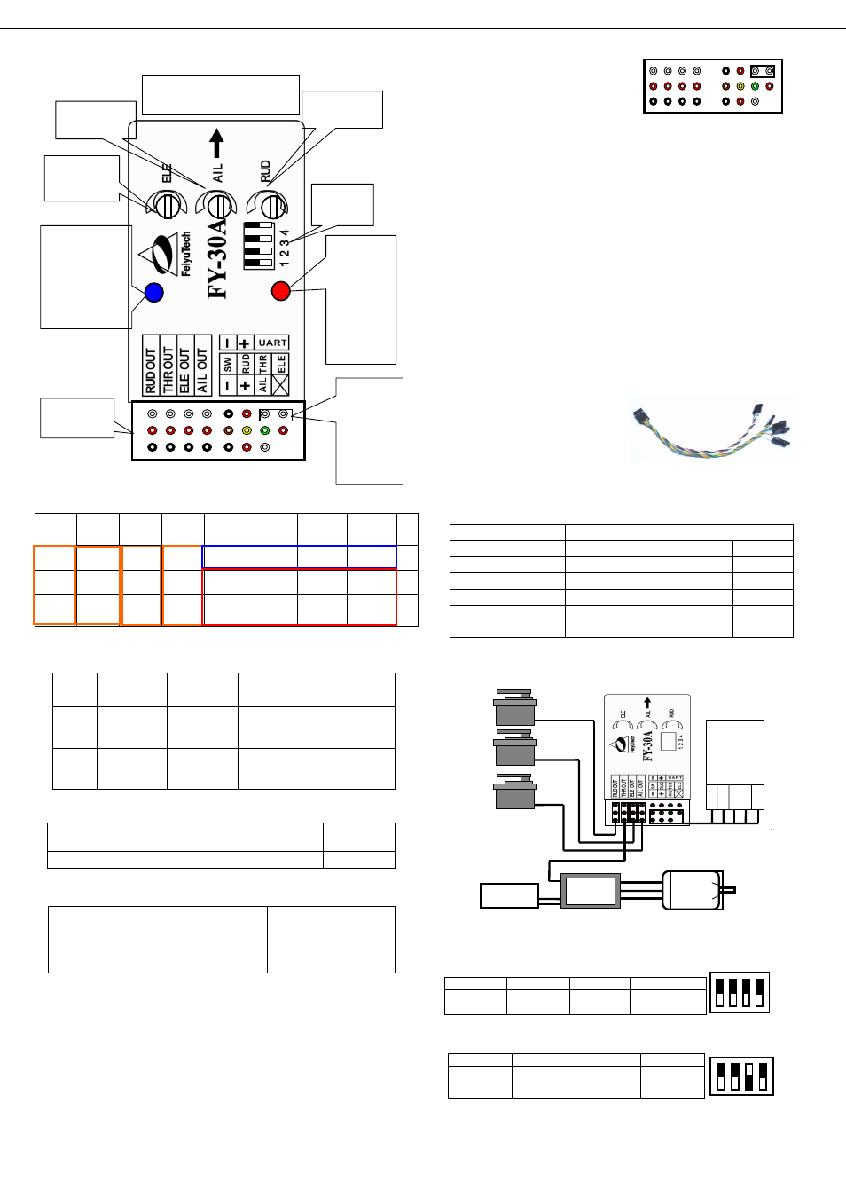
FY-30A interface
Pin interface to sort the list
DIP Switch Function:
Switch
numbe
r
1
2
3
4
ON
For Factory
use only
Flight Mode
Selection
Flight Mode
Selection
Adjust flight
patterns
OFF
Always OFF
position
Flight Mode
Selection
Flight Mode
Selection
Normal mode
Blue LED
Blue LED
Continuous
flashing
On Solid
Single flash
Flight Mode Status
manual mode
Auto Stabilization
3D mode
Red LED
Gyroscope initialization (re-setting):
Out of the box, the FY-30A has been fully initialized. However, if the
following conditions occur, resetting the gyro is recommended:
1. The device has not been used for a long time.
2. There is a change in environmental temperature of over 30 degrees.
3. When the red LED light flashes even when the aircraft is stationary.
Initialization / Reset Procedure
Install the jumper as shown in this picture:
Power-ON the FY-30A and keep it stationary for at least 20 seconds.
You will notice the red light blink at
two different rates (or turns off). Gyro
re-setting is complete. Disconnect
power, unplug the jumper and keep it
in a safe place for future use).
NOTE:
Carry out this re-setting procedure only if the 3 conditions (above)
occur. It is not recommended to regularly reset the gyro. It is not
necessary.
The stabilizer unit does not need to be in a horizontal position
during initialization. However, you must ensure there is no vibration
during this process. If you suspect shaking had occurred, just restart the
resetting process.
FY30A power supply
FY30A working voltage = 5 to 6V.
The FY30A require stable power input. Therefore, we highly
recommend using an External BEC power supply with minimum 3A
output. The higher the better.
Be sure to remove the Red wire from your ESC plug if using an
external BEC.
BEC should be plugged into your RC Receiver. Power is sent to
the FY-30A via Channel 1 input.
FY-30A colour coded cable to
RC
Receiver:
RC Receiver Requirement
a) FY-30A require at least a 5
channel receiver
b) Plug in the cable into the FY30A and connect to the RC Receiver
following these colour codes:
c) Note Channel 5 will output the signal to control the 3 flight
modes of the FY-30A. Therefore assign a 3-way or 2-way switch to this
channel.
DIP Switch Setting
DIP Switch Setting
a) FY3OA connection for traditional aircraft layout:
b) FY30A connection for flying wing aircraft (with or without Rudder):
AIL OUT
ELE OUT
THR OUT
RUD OUT
Differential
Servo 1
Differential
Servo 2
ESC
Rudder
servo
8
7
6
5
4
3
2
1
N
O.
Rudder
out
Throttle
out
Elevator
out
Aileron
out
Ground
Power
TX
RX
A
Power
Power
Power
Power
CH5
(Switch)
CH 4
(Rudder)
CH 3
(Throttle)
CH 2
(Elevator)
B
Ground
Ground
Ground
Ground
Ground
Power
CH 1
(Aileron)
NULL
C
Red LED
OFF
Aircraft is stationary
but Red LED Flashes
ON Solid
Status
Indicator
Normal
Need to initialize
the gyro
High Vibration Detected.
Does not meet system
requirement.
Wire color
Receiver channel
White (red and black)
Aileron
Channel 1
Orange
Elevator
Channel 2
Green
Throttle
Channel 3
Yellow
Rudder
Channel 4
Brown
Controlled via 3-Way or 2-Way
switch
Channel 5
AIL OUT
ELE OUT
THR OUT
RUD OUT
Aileron
servo
Elevator
servo
ESC
Rudder servo
ON
OFF
4
3
2
1
B
A
8
C
7 6 5
4 3 2 1
1 2 3 4
OFF
ON
POINT ARROW FORWARD
(TOWARDS FLIGHT DIRECTION)
Aileron
sensitivity knob
Elevator
sensitivity
knob
Rudder
sensitivity knob
Function
DIP switch
Red LED:
Solid ON
indicates
vibration is
too severe.
Flashes when
stationary:
indicate need
for gyro
initialization.
Blue LED: Flight
mode indicator.
Always On: Auto
Stabilization
Single flashing: 3D
mode.
Continuous flash:
manual mode.
Interface pin
panel
Jumper
installed
during gyro
initialization.
Do not insert
jumper
during
normal use.
B
A
8
C
7 6
5
4 3 2
1
Battery
ESC
(CH 3)
Electric
motor
RC
Rec
eiv
er
ELE
THR
RU
D
AIL
CH5
RUD OUT
ELE OUT
AIL OUT