Assembly instructions – Eskimo 15300 User Manual
Page 4
Check for parts online at
www.GetEskimo.com or call 800-345-6007 M-F 8-5 CDT
4
Operator's Manual
ESKIMO
®
QuickFlip
™
1
ASSEMBLY INSTRUCTIONS
Tools needed – (2) 7/16” wrenches, a Phillips head screwdriver,
rubber mallet (optional), and a cordless drill (optional).
Assembly Note: This ice shelter should be assembled in a
garage or basement setting due to the time and length of
assembly. Identify and familiarize yourself with all parts
and hardware before assembly. Allow 1-3 hours for assem-
bly.
Assembly Note: The use of a cordless drill with socket will
make assembly of your ice shelter much quicker. Be sure to
set the drill speed on low so you do not over tighten any nut
and bolt combination.
Assembly Note: If a tracking kit is purchased with the
shelter it should be mounted to the sled before assembly
of the ice shelter for convenience.
Important Assembly Tip: Do NOT fully tighten any nut and
bolt combination until instructed in later notes. This will
help hole alignment of all parts.
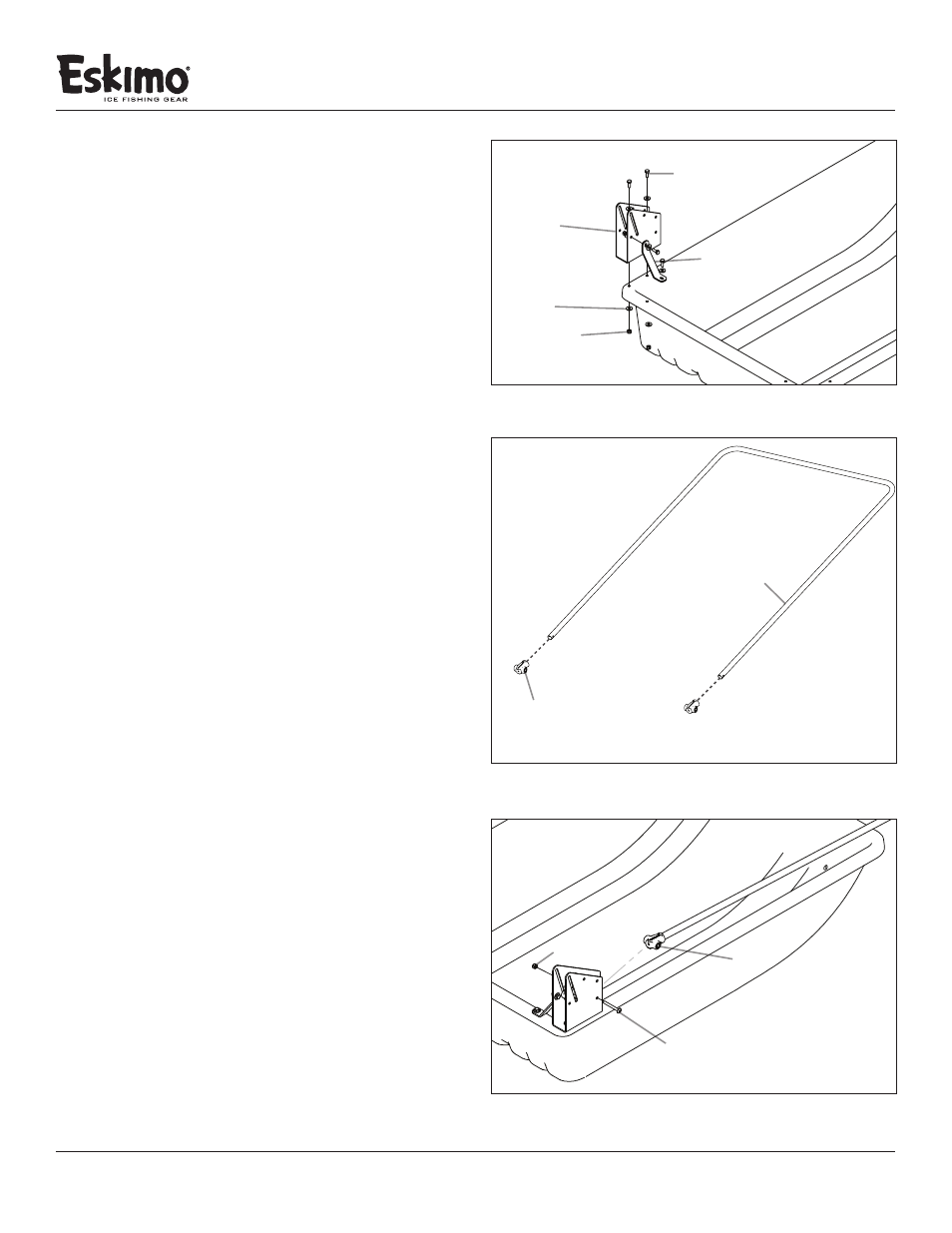
1. Attach the Hinge (15062) to the upper lip of the tub using (2)
¼-20 X 3/4” bolts, (4) ¼” washers and (2) ¼-20 nylock nuts.
Repeat this step on the opposite side. SEE FIGURE 1
2. Attach the (1) hinge support brace (11203) to the hinge(15062)
using (2) ¼-20 x 3/4” bolts, (4) ¼” washers, and (2) ¼-20 nylock
nuts. Repeat this step on the opposite side. SEE FIGURE 1
Note: If the hole alignment is off or looks too far apart,
rotate the hinge support brace and try again. This part will
only bolt on one way.
3. Tighten all hardware used to complete this portion of
assembly instructions.
4. Locate the (8) pole caps (15295) from the parts bag. Using
(6) of the pole caps, slide one pole cap on to each end of (3)
frame support poles (15017). The holes in the frame support
poles must line up with the holes in the pole caps. SEE
FIGURE 2
Note: The (2) additional red pole caps will be used for a later
step. A rubber mallet may be helpful for this step.
5. Starting with the hole #1 on each of the (2) hinges (15062),
attach the (3) frame support poles (15017) from the previous
step, to the left and right hinges using (2) ¼-20 x 2-1/4” bolts,
and (2) ¼-20 nylock nuts. Repeat this step for hole #2 and #3
on each of the hinges. SEE FIGURE 3
FIGURE 1
hinge
¼” washer
¼-20 nylock nut
FIGURE 2
frame support pole
pole cap
#
1
FIGURE 3
¼-20 X 2-1/4” bolt
¼-20 nylock nut
¼-20 X 3/4” bolt
hinge support brace
#
2
#
3
pole cap
#
4