ENMET PID-Guard User Manual
Page 18
PID-G
UARD
ENMET Corporation
16
5.4 Sensor Replacement
W
ARNING
:
Power must be removed from the
PID-G
UARD
before this or any internal procedure. Failure to do so may cause
damage to equipment, bodily injury or death.
Sensors should be replaced when they can no longer be calibrated. Replacement sensor part numbers are listed in Section 6.0
of this manual. If you do not know the proper part number for your sensor, have the
PID-G
UARD
serial number available when
contacting your Distributor or
ENMET
Corporation Technical Support.
Remove, the 4 retaining screws from
PID-G
UARD
lid and 2 retaining screws form sensor manifold, see Figure 6
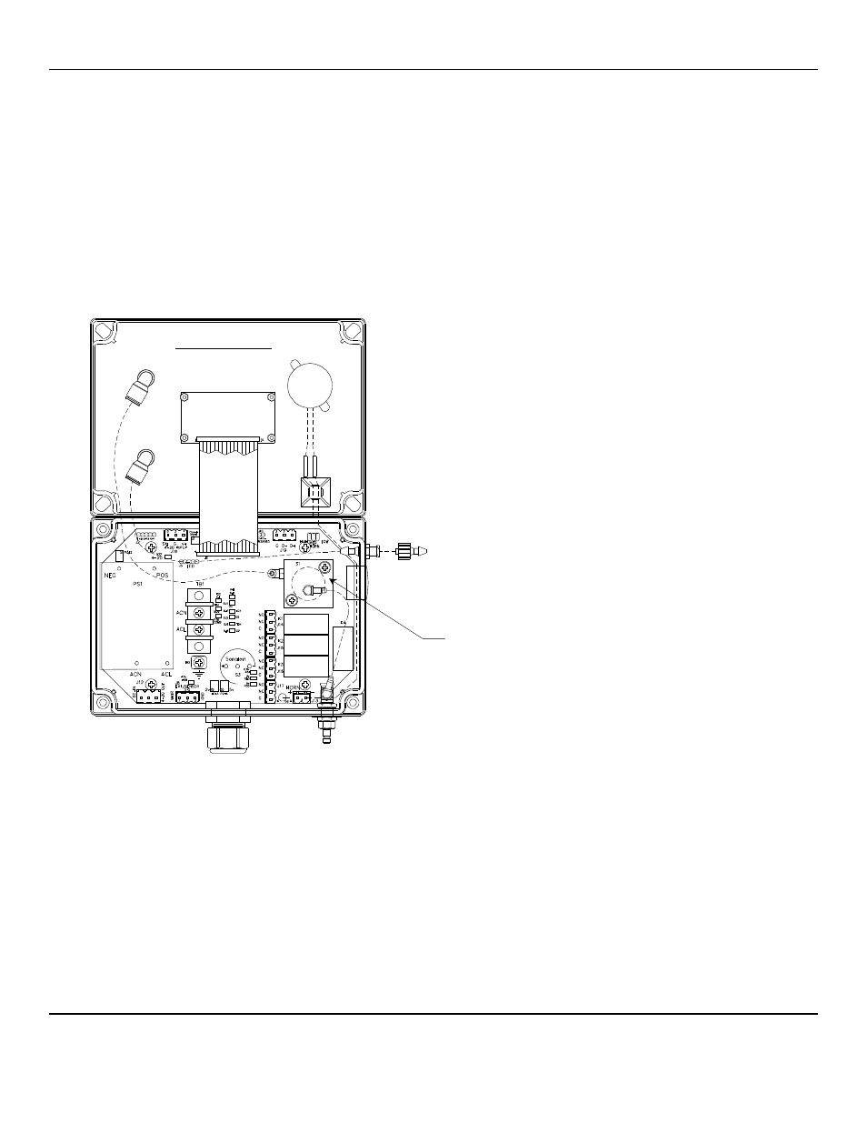
Remove, the sensor assembly from the PCB/sensor manifold, see Figure 8.
Insert, the new sensor assembly and replace sensor manifold and 2 retaining screws.
Replace, lid and the 4 retaining screws.
Re-supply power to the
PID-G
UARD
Figure 8: PID-G
UARD
Sensor Replacement
After the new sensor assembly has been installed, it is suggested to allow the sensor to stabilize for 3 – 4 hours.
A Factory calibration must be performed.
After entering the Maintenance menu, press and hold the
M
ENU
button for 2-4 seconds while viewing the Zero menu.
After 2-4 seconds, an F will appear on the far right hand side of the display. The F indicates that the instrument is in Factory
mode.
Perform the calibration Zero and Span procedures as outlined in Section 5.2. Be sure that the F is present when selecting the
Zero and Span functions.
The Factory calibration sets a calibration window for future standard instrument calibrations.
PCB/Sensor
Manifold
Cover Inside View
Opened Upward
Attached to Base