Fflow:y, 0 operation – ENMET MedAir 2000 User Manual
Page 12
ENMET Corporation
M
ED
A
IR
2000
8
4.0 Operation
4.1 Normal Operation Condition
With the M
ED
A
IR
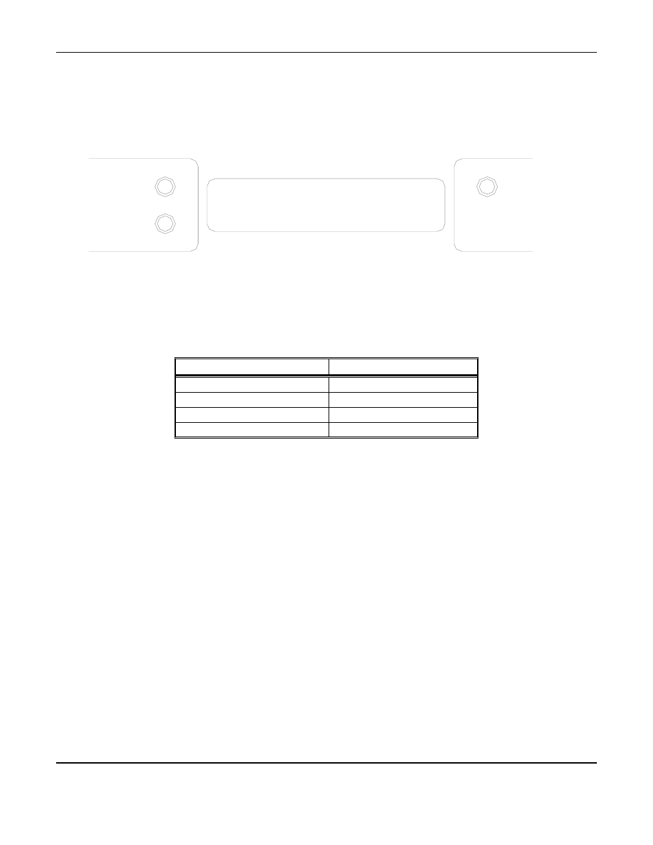
2000 installed as described in section 3, and in clean air, the POWER green LED is on, the display
is lit, the flowmeter reads approximately 2
SCFH
, and the information on the display is as shown in Figure 4 Display,
for the sensor(s) installed in the M
ED
A
IR
2000.
The red alarm and fault LEDs are not lit.
Example of display with Dew Point and Oxygen option installed
Figure 4: M
ED
A
IR
2000
Operational Display
4.2 Alarm Set Points
There is one alarm set point for CO and dew point, and two for oxygen. The factory settings of these alarm set points
are shown in Table 4.
Table 4: Factory Alarm Set Points
Gas
Set Point
Carbon Monoxide
10 ppm
Dew point
39°Fahrenheit at 55
PSIG
Oxygen Deficiency
19.5 % by volume
Oxygen Abundance
23.5 % by volume
These alarm set points can be changed within limits; see the maintenance section of this manual for the procedure.
If the CO concentration increases above that of the alarm set point, the associated red LED is lit, the associated
relay changes state, and the audio alarm is activated.
If the dew point increases above that of the alarm set point, the associated red LED is lit, the associated relay
chances state, and the audio alarm is activated.
If the oxygen content of the sample air decreases below the deficiency alarm set point, the associated red LED is
lit, the associated relay chances state, and the audio alarm is activated.
If the oxygen content of the sample air exceeds that of the abundance alarm set point, the associated red LED is lit,
the audio alarm is activated, and both the oxygen alarm relay and the oxygen high alarm relay change state.
There is one alarm LED for both the deficiency and abundance alarms.
4.3 Alarm Latching
An instrument is shipped with the alarms in the non-latching mode. The alarms may be independently configured in
the non-latching mode by use of the maintenance menu.
I
N THE LATCHING MODE
: at the cessation of the condition which causes an alarm, the alarm indications do not
cease, and the alarm relay contacts do not revert to the non-alarm state, until the ALARM ACKN/AUDIO
DEFEAT switch is pressed. An alarm can also be acknowledged by pressing the switch during the alarm
condition; then at the cessation of the alarm condition, alarm indications cease and alarm relays revert to the non-
alarm state. After an alarm is acknowledged, alarms in the latching configuration are re-armed to latch at the next
alarm condition.
I
N THE NON
-
LATCHING MODE
: at the cessation of the condition which causes an alarm, the alarm indications
automatically cease, and the alarm relay contacts revert to the non-alarm state.
000
PPM
20.9%
037
o
F
FLOW:y
CO
PPM
O
2
%
DEW
POINT