ENMET MedAir 2000 User Manual
Page 11
M
ED
A
IR
2000
ENMET Corporation
7
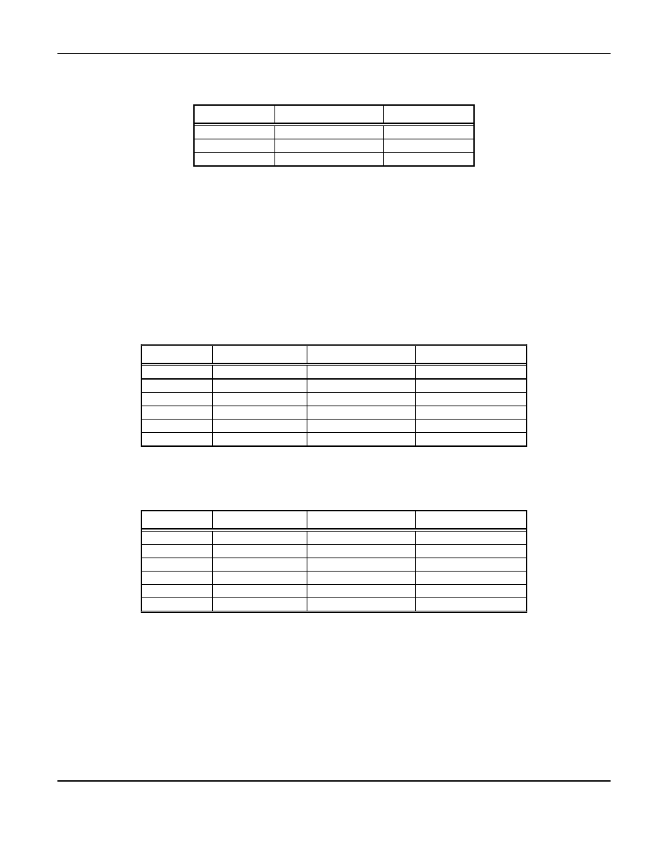
In addition, there is a fault relay, which changes state whenever the instrument is in a fault condition.
The contact positions are given in Table 2:
Table 2: Fault Relay Contacts
Position
Function
Contact
13
Fault
NC
14
Fault
C
15
Fault
NO
The coil of this relay is energized when the instrument is in the non-fault state; the contact conditions given above are
for the non-energized state, which is identical to the fault state.
These relay contacts can be used to operate auxiliary alarms or other functions. Punch a hole at the bottom of the left
side of the enclosure for a wire exit, and use appropriate cable and fittings to preserve the NEMA-12 rating of the
enclosure.
3.4.2 Optional 4-20mA Outputs
Isolated 4-20 mA outputs are available for data logging or other purposes. An output is supplied for each sensor
supplied in a particular instrument, and can be added when a sensor is added in the field. When all three sensors are
supplied, these outputs are available on the terminal strip in the positions given in Table 3:
Table 3: Outputs for 4-20mA for S/N 599 and below
Position
Channel
Function
Range
16
CO
Ground
4 mA = 0 ppm
17
CO
+ 4 to 20 mA
20 mA = 100 ppm
18*
DP
Ground
4 mA = –100°F
19*
DP
+ 4 to 20 mA
20 mA = +50°F
20*
O
2
Ground
4 mA = 0%
21*
O
2
+ 4 to 20 mA
20 mA = 25.5%
*When two of the three sensors are supplied, one sensor is for CO, and the output for this sensor is on positions 16
& 17 as shown in Table 3 above. The second output is on positions 20 & 21. Positions 18 & 19 are not used.
Table 3A: Outputs for 4-20mA for S/N 600 and above
Position
Channel
Function
Range
16
CO
Ground
4 mA = 0 ppm
17
CO
+ 4 to 20 mA
20 mA = 100 ppm
18
DP
Ground
4 mA = –100°F
19
DP
+ 4 to 20 mA
20 mA = +50°F
20
O
2
Ground
4 mA = 0%
21
O
2
+ 4 to 20 mA
20 mA = 25.5%
Wiring requirements are the same as for the relays.
3.5 Initial Calibration
All instruments are calibrated at the factory. You may, if a calibration kit is available, calibrate the CO and O
2
channels of the instrument 24 hours after installation. The dew point sensor can not be calibrated in the field. See
Section 5.0, Maintenance, for calibration instructions. After calibration, be sure to return the red sample-calibrate
valve handle to the down position, pointing toward the sample input port.