2 internal electronic circuitry, Figure 2: circuit board with terminal blocks – ENMET ISA-44-RAL-OD User Manual
Page 10
ENMET Corporation
ISA-44RAL-OD / ISA-44RAH-OD
6
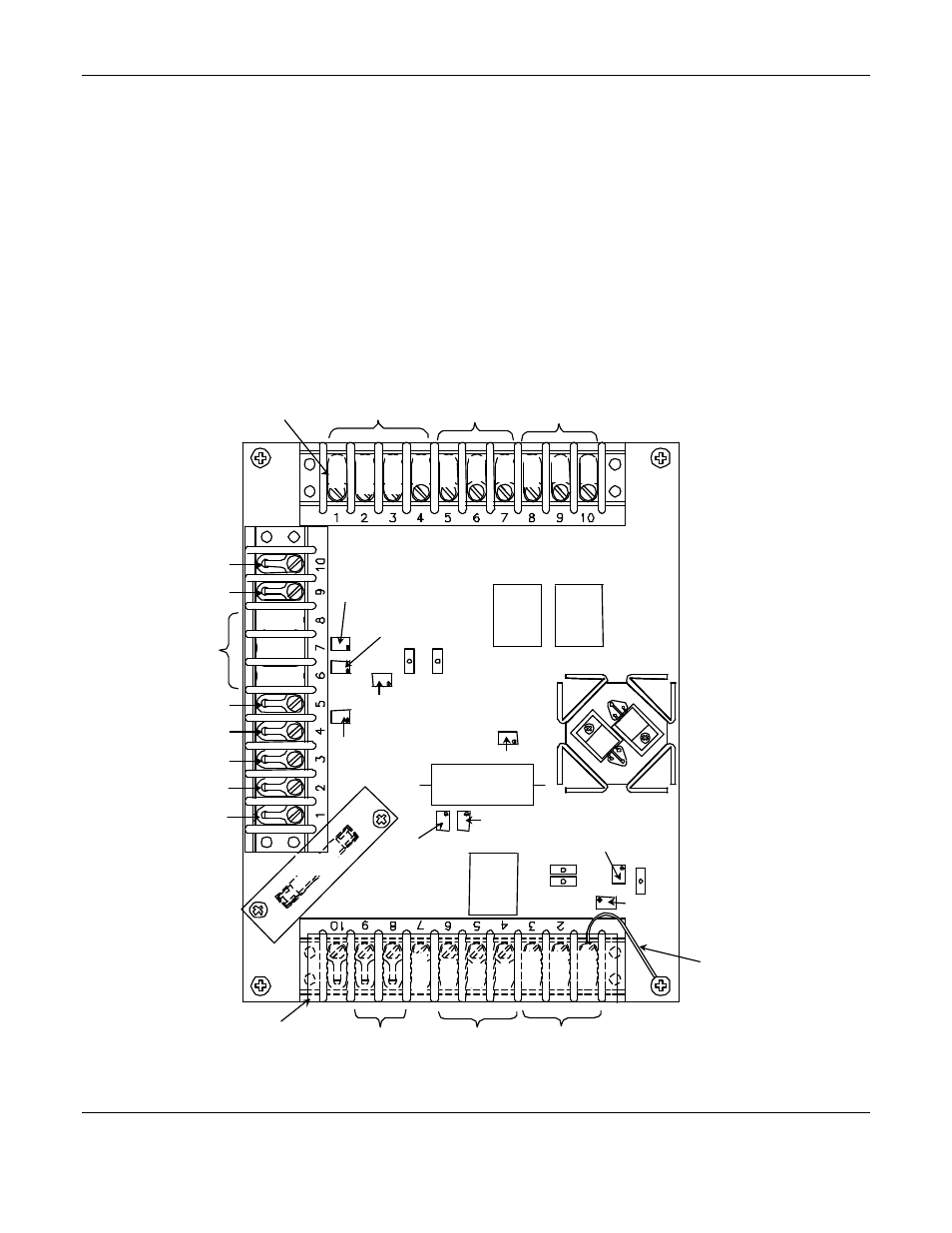
3.2 Internal Electronic Circuitry
Figure 2 shows the circuit board and terminal blocks housed inside the hinged oiltight control unit. Specific relays and
adjustments are defined:
I
NTERNAL
R
ELAY
C
ONTACTS
: Relays can be used to activate an external remote alarm system when a hazardous CO level
is detected. These are double-pole relays (Figure 2 upper right) with terminals "normally open"(N.O.), "normally
closed"(N.C.), and "common"(COM.) (See Figure 3 and Section 4.0 for relay contact hook-up). There is one relay for
each alarm level (2 alarm levels for CO, 1 for oxygen).
N
OTE
:
Relay contacts are shown in the de-energized state (power off).
N
OTE
:
If you want the relays to activate auxiliary equipment when the power to the control unit is interrupted, you
must connect the relays to an external power source. See Figure 3a.
P
OTENTIOMETERS
: The unit has 9 potentiometers. These adjust critical circuit resistances and are essential to calibration
procedures.
Figure 2: Circuit Board with Terminal Blocks
TB1
Relay
K 1
TB2
Relay
K 2
Relay
K 3
TB3
TP4
DC-Gnd
Relay
High Level
Relay
Low Level
Lights
DC Ground
MOS Sensor
O2 Relay
O2 Cell
115 VAC
Power
Terminal
Cover
Case
Ground
TP5
TP1
TP2
TP3
CO Meter
+
CO Meter
–
O2 Meter
–
O2 Meter
+
DC Ground
Purge
+12 VDC
High Level
Alarm Set
Low Level
Alarm Set
Meter
Adjust
Purge Adjust
Heater
Adjust
Low Level Set
O2 Alarm Set
Meter Full Scale Adjust
Null Adjust
Green
Amber
Red
N.O.
N.C.
COM
COM
COM
N.O.
N.C.
COM
Green
N.O.
N.C.
Amber
Black
White
–
+
Green
White
Black
Fuse