Table 2: remote sensor assembly wiring, Figure 4: interior view of sensor assembly – ENMET ISA-40M User Manual
Page 8
ENMET Corporation
ISA-40M Oxygen Monitor
6
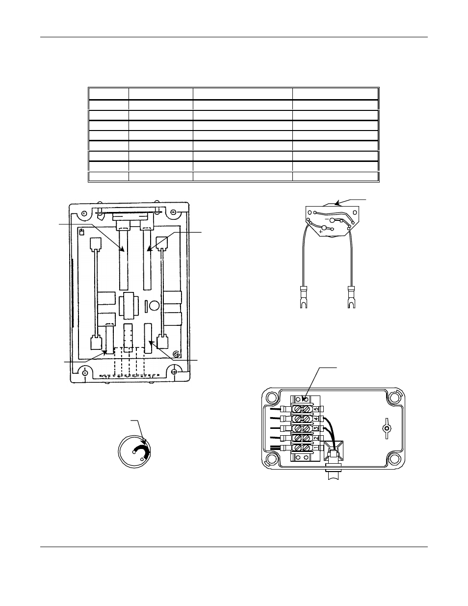
3.2.2 Remote Sensor Assembly Wiring
See Figure 4 for location of terminal blocks.
Table 2: Remote Sensor Assembly Wiring
Channel
Signal
Control Unit Connection
Sensor Connection
1
Oxygen Cell (–)
TB1 – 1 O2 –
TBS – 3
1
Oxygen Cell (+)
TB1 – 1 O2 +
TBS – 4
2
Oxygen Cell (–)
TB1 – 2 O2 –
TBS – 3
2
Oxygen Cell (+)
TB1 – 2 O2 +
TBS – 4
3
Oxygen Cell (–)
TB2 – 3 O2 –
TBS – 3
3
Oxygen Cell (+)
TB2 – 3 O2 +
TBS – 4
4
Oxygen Cell (–)
TB2 – 4 O2 –
TBS – 3
4
Oxygen Cell (+)
TB2 – 4 O2 +
TBS – 4
Figure 4: Interior View of Sensor Assembly
Internal View: Remote Sensor Assembly
TBS
Remove Shoring
Clip or Spring
Bottom View O2 Sensor
••Center Pin – Negative
••Outer Pin + Positive
O2 Cell Circuit Board
w/cell installed on circuit side
O2 Cell
TB4
TB2
TB1
TB3
T
B
3
T
B
4
T
B
2
T
B
1
T
B
5
TB7
ISA-40M Interior View
- Formaldemeter htV (14 pages)
- PPM Formaldemeter™ htV-m (19 pages)
- PGD2 (34 pages)
- PGD2Manual.pdf (28 pages)
- RECON/4 (10 pages)
- RECON-4 (17 pages)
- RECON-IS (15 pages)
- RECON/B SERIES (17 pages)
- RECON Series (16 pages)
- OMNI-4000 (72 pages)
- QUADRANT (26 pages)
- SMARTLOGGER (19 pages)
- SPECTRUM (32 pages)
- SPECTRUM CO-RAL (18 pages)
- SPECTRUM ON-LINE (30 pages)
- SPECTRUM-RAL (15 pages)
- SPECTRUM-RAL-DC (17 pages)
- SPECTRUM SP (20 pages)
- TARGET (36 pages)
- TDX Series (8 pages)
- TX-2000 (24 pages)
- AM-5150 (23 pages)
- AM-5175 (21 pages)
- ENG – 97D STAND-ALONE (12 pages)
- GSM-60 (39 pages)
- ISA-60M with MRI-5175 (28 pages)
- MRI-5175 (2 pages)
- MEDAIR 2200 (40 pages)
- PROAIR 2200 (40 pages)
- CP-60 (23 pages)
- EX-5100 (18 pages)
- EX-5175-EC (16 pages)
- ISA-200-RAL (O) (24 pages)
- ISA-40 (19 pages)
- ISA-44-2OD (32 pages)
- ISA-44-RALE-OD (38 pages)
- ISA-44-RAL-OD (28 pages)
- ISA-M (15 pages)
- ISA-RAL-M (22 pages)
- MedAir 2000 (30 pages)
- CD-1300-ST (13 pages)
- EX-5120 (18 pages)
- EX-5130 (16 pages)
- EX-5150-MOS (19 pages)