0 installation – ENMET ISA-40M User Manual
Page 5
ISA-40M Oxygen Monitor
ENMET Corporation
3
3.0 Installation
3.0 Installation
W
ARNING
:
This equipment is not for use in hazardous combustible atmospheres as defined by the national
electrical code. Use in such atmospheres may result in property damage, injury or death
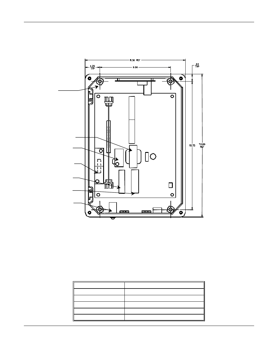
Figure 2: Mounting Dimensions
3.1 Control Unit Mounting and Power Hook-up
Use an appropriate fitting for conduit when supplying power to the unit.
1. Choose a suitable location for mounting the electronics control unit. See Figure 2 for mounting dimensions.
N
OTE
: All dimensions are given in inches.
2. Apply 110 V
AC
and/or 12 V
DC
power to the appropriate terminals on TB5 and TB3. Refer to the Wiring
Information table. Both 110 V
AC
and 12 V
DC
power can be applied together; the 12 V
DC
is standby power
source;
DC
current will flow only when the
AC
power is interrupted.
Table 1: Power Supply Wiring
Power supply
ISA-40M Control Unit connection
110 V
AC
H
OT
TB5 HOT
110 V
AC
N
EUTRAL
TB5 NEUT
AC ground
TB5 GND
12 V
DC
TB3-3 + V
DC
DC ground
TB3-1 or TB3-2
Mounting Holes
4 places
Fuse
Circuit Breakers
Transformer
Protective
Standoff cover
TB3
TB5