ENMET ISA-40M User Manual
Page 7
ISA-40M Oxygen Monitor
ENMET Corporation
5
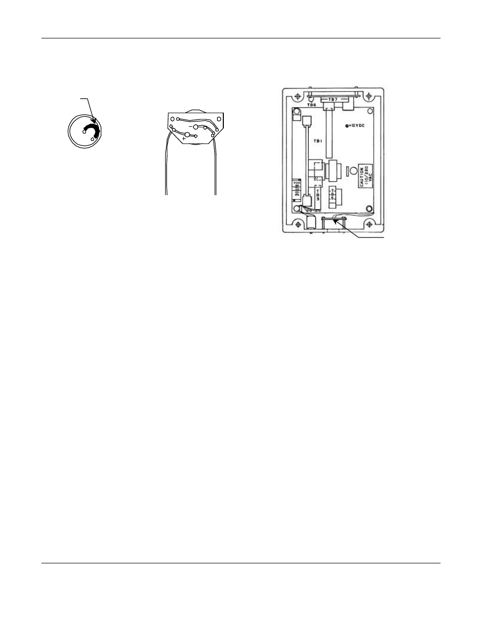
ISA-40M Interior View
Figure 3: Oxygen Cell Installation
3.2 Oxygen Cell Installation
W
ARNING
:
The transducer cell must be installed and the oxygen monitor must be operational prior to using
cryogen with the MRI equipment magnet. If the monitor is not operational, there is a risk of
asphyxiation should a leak occur.
3.2.1 Oxygen Cell Installation Inside of Control Unit
The oxygen detection transducer cell is mounted inside the unit. The cell is packaged in a nitrogen filled plastic bag to
prevent depletion of useful life before installation. Do not open or puncture the bag before installation to insure best
performance of cell.
1. Remove 4 cover screws to open the control unit and remove screws to remove cell circuit board. See Figure 1 & 3.
2. Carefully remove the cell from the package.
3. Remove the metal shorting clip (or spring) from cell pins. See Figure 3.
4. Plug the cell into the component side of the cell circuit board; center pin to center hole. See Figure 3. Place the
board in the enclosure and replace the screws to secure the cell and circuit board.
5. Wait at least four hours for the cell to stabilize before setting the gain. The cell needs time to adjust to oxygen in
air, since it has been packaged in pure nitrogen.
6. The life expectancy of oxygen cells is about 14 months; warranty is six months. Remove the cell serial number
tag from the plastic bag, and stick it to the inside of the enclosure. In case of cell warranty problems, refer to this
serial number.
N
OTE
: If all channels are used with remote sensor assembly, remove the O2 Cell Circuit Board from the interior of the
ISA-40M. Reference Table 2 channel 1.
Remove Shoring
Clip or Spring
Bottom View O2 Sensor
••Center Pin – Negative
••Outer Pin + Positive
O2 Cell Circuit Board
w/cell installed on circuit side
O2 Cell
Circuit Board
See note below