0 maintenance – ENMET ISA-40M User Manual
Page 13
ISA-40M Oxygen Monitor
ENMET Corporation
11
5.0 Maintenance
5.0 Maintenance
5.1 Cell Aging
The output of the cell decreases with cell usage. The change is very small during the operational life of the cell, 12-14
months, and is compensated by changing the gain to cause the meter reading to be 20.9% in fresh air. Gain reset and
rough test (Sections 3.2.3 and 4.1) should be accomplished every 4 – 6 weeks.
N
OTE
: When adjusting the gain, if the air at the sensor locations is suspected to be depleted in oxygen, bottled air and
a calibrator should be used; see section 8.2.
5.2 Cell End-of-Life
When the electrodes in the transducer cell are finally depleted, the cell output terminates rather quickly. The first
indication that this is occurring is generally an inability to adjust the gain to yield a 20.9% reading in fresh air. Then
the cell output decreases until the channel is constantly in alarm. To install a new cell, follow the procedures given in
sections 3.2.1 and 3.2.2. If installing a cell in a remote sensor assembly with audio alarm, disconnect the ground side
of the sensor assembly audio alarm during this process to avoid spurious alarms while changing the cell; reconnect it
when done.
5.3 Circuit Alignment
Each ISA-40M system is aligned at the factory; however, due to prolonged use, oxygen cell replacement and assorted
other circumstances, it may become necessary to realign the circuitry. If the unit is in constant alarm, the oxygen
micro fuel cell has probably expired. Proceed to the cell replacement section 5.2, then come back to this one. The
procedure for realignment is not difficult, but be aware that any deviation from the procedure described below voids
the warranty. If you have any doubts about the procedure, contact ENMET personnel.
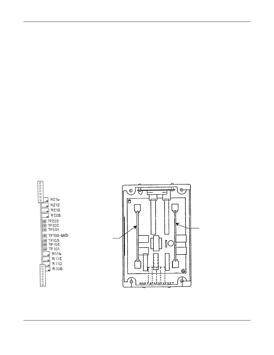
The only tools necessary are a digital voltmeter and a small screwdriver. This procedure is given for an S-2 oxygen
cell, ENMET P/N 67013-008 as furnished as a replacement cell; this cell has a grey label. Refer to Figure 7 for test
point and potentiometer locations.
Edge view of Circuit Board
Interior view of 4 channel ISA-40M
Figure 7: Location of Circuit Boards, Test points and Potentiometers
Channel 3 & 4
Circuit Board
Channel 1 & 2
Circuit Board