Figure 1: s, Features 2.2 installation, 1 mount enclosure – ENMET SPECTRUM ON-LINE User Manual
Page 7: 2 relay contacts, 3 turn on
Spectrum ON-LINE
ENMET Corporation
3
Figure 1: S
PECTRUM
O
N
-L
INE
Features
2.2 Installation
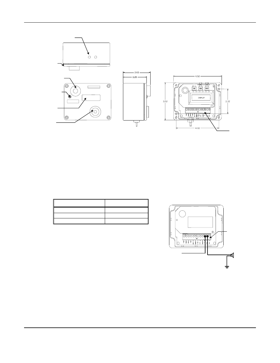
2.2.1 Mount Enclosure
Mount enclosure at an appropriate location using the four mounting holes accessible inside the enclosure. See Figure 1
Dimensions are in inches.
2.2.2 Relay Contacts
One set of alarm relay contacts are accessible on a spring-clamp terminal strip inside the enclosure after removing the
cover. See below for Terminal strip locations and suggested relay wiring.
Terminal position
Connection
10
C
11
NC
12
NO
Contact position refers to the unpowered condition that is also the
alarm condition. Relay contacts are rated at 2amps. Instrument
ground is accessible at terminal strip locations 2 and 3, and +12
V
DC
is available at locations 5, and 6. When powering an
auxiliary device with +12 V
DC
, do not overload the power supply
(exceed 200mA). If desired, the relay wires exit through the hole
on the right side of the enclosure. Remove the hole plug and use
an appropriate strain relief. The strain relief is available from
ENMET; see Section 5.0, Replacement Parts List.
Suggested Relay wiring
2.2.3 Turn On
Plug the power supply into a 110 V
AC
outlet. The display should read “0000” within ten seconds when the monitor is
supplied with uncontaminated air.
N
OTE
: Instruments using biased sensors, this time is extended to 4 minutes and stabilization may take as long as 1
hour. See Table 1.
Exterior View
Interior View
Sensor Housing
Side View
Top View
Pushbutton Switches
Audio Alarm
Display
Cover
Visual Alarm
Terminal Strip
110V
AC
or
24 – 24V
DC
V
AC
Neutral or –24 – 24V
DC
V
AC
High or +24 – 24V
DC
Strobe or Horn
C NC NO
Terminal Strip