Solder practice – Elenco Practical Soldering Project Kit User Manual
Page 7
-6-
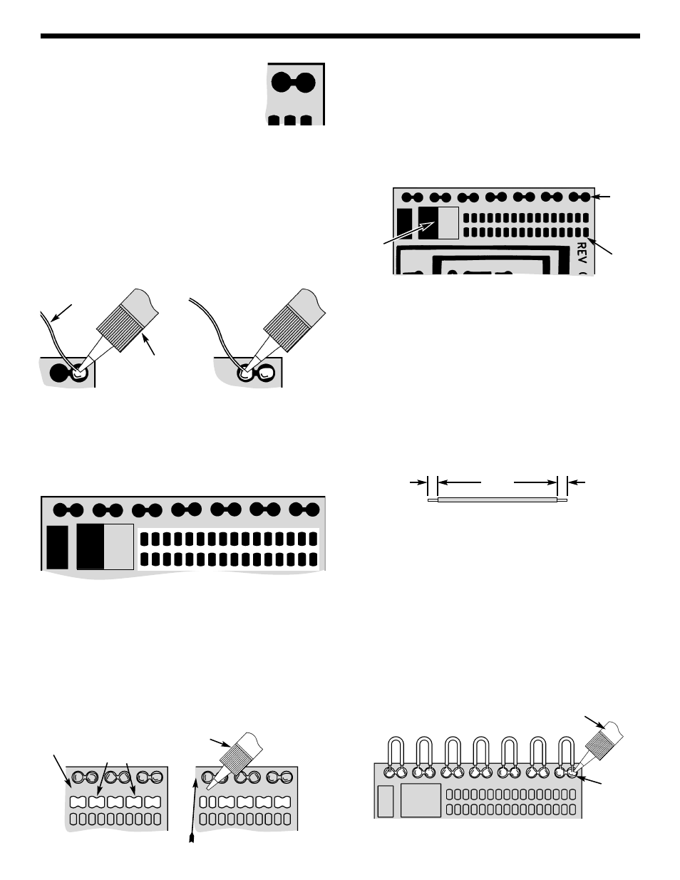
Double Pads
Before we begin to assemble and solder
the components to the solder practice
PC board, we will start first by practice
soldering to the double pads on the
edge of the PC board (see Figure 3).
1. Apply a small amount of solder to the iron tip. This
allows the heat to leave the iron and onto the foil.
2. Place the iron on the top half of pad and then
apply the solder (see Figure 4). Allow the solder
to flow around the pad. Then, remove the solder
and the iron and let the solder cool. The solder
should be neat and smooth.
3. Repeat step 2 on the top row of the pads (see Fig. 4).
Single Pads
Now practice using the single pads. Use the same
soldering procedures as the large double pads. Be
sure there are no solder bridges between the pads.
(Refer to the Solder Bridge Section below).
Solder Bridge
Solder bridges occur when solder runs between
circuit paths and creates a short circuit. This is
usually caused by using too much solder. Using the
top row of single pads, try intentionally to make a
solder bridge on each section (see Figure 5). Then,
remove it by simply dragging your soldering iron
across the solder bridge as shown. It is best to wipe
the iron tip with a wet sponge to remove the solder.
You can also use solder wick as described on page 7.
Solder Resist
The PC board is covered with solder resist over
areas that are not to be soldered. This is done to
reduce soldering shorts to adjacent metal runs. On
the large pad, note that half of the pad is covered
with solder resist. Try soldering to the covered pad.
You will find that it is impossible to solder.
Note: There are three pieces of wire included.
Save one piece for the speaker assembly.
Tack Soldering
You will make 14 tack solder connections by
soldering seven wires to the top row of pads.
1. Cut seven 1 1/2” wires and strip 1/8" insulation off
both ends (see figure below).
2. Place the iron and the wire on top right pad as
shown in Figure 7. Allow the solder to flow around
the wire. Then, remove the iron and let the solder
cool. You may need to add some more solder.
The solder should be neat and smooth.
3. Pull the wire to make sure you have a good solder
joint.
4. Bend the wire and solder it to the next pad, as
shown in Figure 7.
5. Now solder the remaining wires to the pads as
shown in Figure 7.
Figure 3
SOLDER PRACTICE
Figure 4
Solder
Soldering Iron
Figure 5
Soldering Iron
Drag Iron
Solder Bridges
PC Board
Figure 6 Practice Solder Area
Tack Solder
Pad
Small
Pads
Large
Pads
Figure 7
Soldering Iron
Solder
1 1/2”
(Actual Size)
1/8”
1/8”