Pc board assembly (continued) – Elenco Practical Soldering Project Kit User Manual
Page 13
-12-
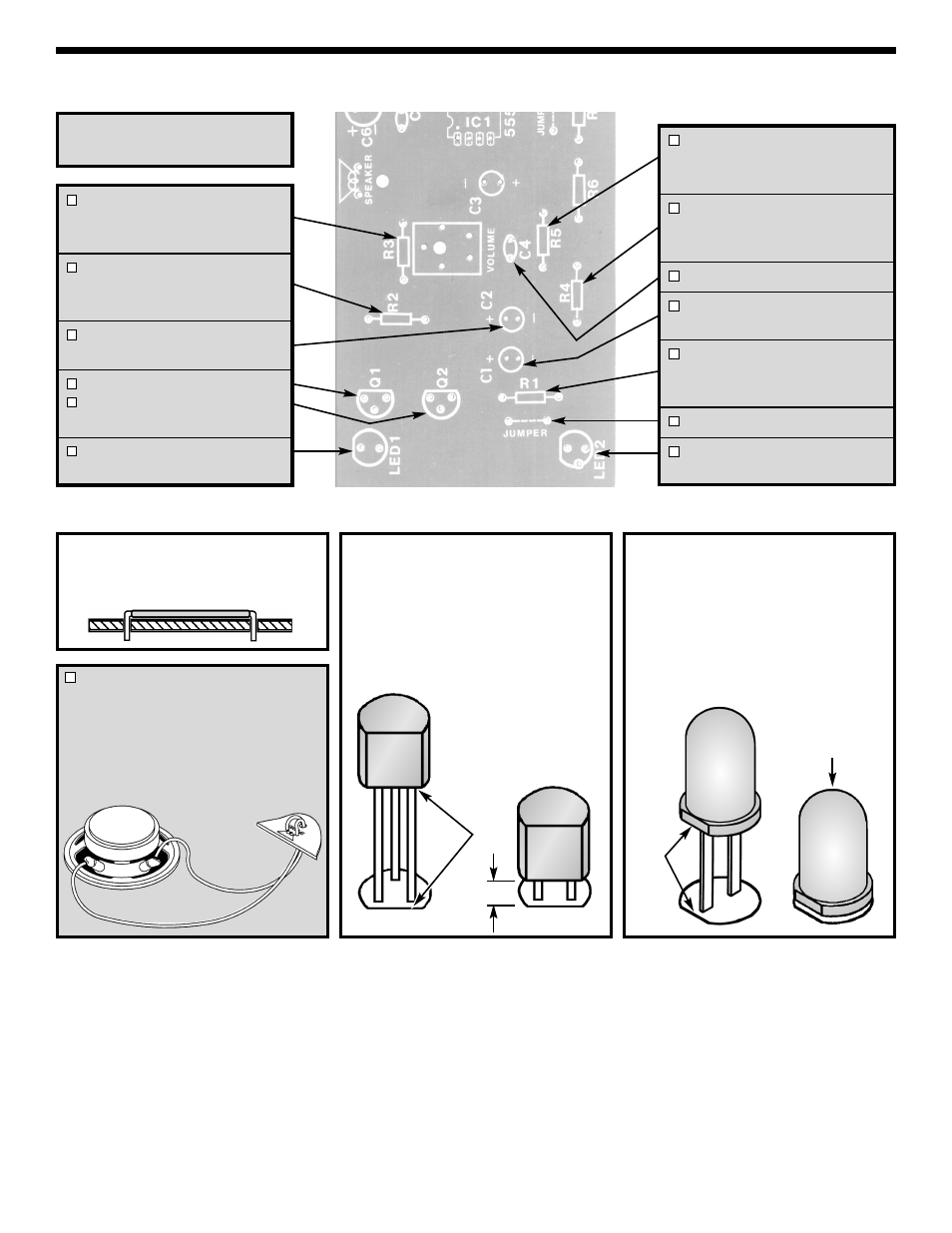
Figure H
Mount the LED onto the PC board
with the flat side of the LED in the
same direction as marked on the PC
board. Be sure to mount the LED
flush with the PC board as shown
below.
Solder and cut off the excess leads.
Figure G
Mount the transistor with the flat side
in the same direction as marked on
the PC board. Leave about 1/8” of
space between the transistor and the
PC board as shown below. Solder
and cut off the excess leads.
PC BOARD ASSEMBLY (continued)
Figure F
Cut a 1” wire and strip 1/8” of
insulation off of both ends.
R3 - 68
Ω 5% ¼W Resistor
(blue-gray-black-gold)
(see Figure E)
R2 - 1k
Ω 5% ½W Resistor
(brown-black-red-gold)
(see Figure E)
C2 - 10
μF Electrolytic (Lytic)
(see Figure B)
Q1 - 2N3904 Transistor
Q2 - 2N3904 Transistor
(see Figure G)
LED1 - Light Emitting Diode
(see Figure H)
R5 - 47k
Ω 5% ¼W Resistor
(yellow-violet-orange-gold)
(see Figure E)
R4 - 22k
Ω 5% ¼W Resistor
(red-red-orange-gold)
(see Figure E)
C4 - .02
μF or .022μF Discap
C1 - 10
μF Electrolytic (Lytic)
(see Figure B)
R1 - 470
Ω 5% ¼W Resistor
(yellow-violet-brown-gold)
(see Figure E)
Jumper Wire (see Figure F)
LED2 - Light Emitting Diode
(see Figure H)
Flat
1/8”
Flat
Mount Flush
to PC Board
Cut the 12” wire in half and the strip
1/8” of insulation off of both ends.
Insert the speaker wire through the
PC board as shown. Then, insert
the wires into the speaker holes
and solder. Solder the other end of
the wires to the speaker.
Solder the following parts to
the PC board.