Pc board assembly – Elenco Practical Soldering Project Kit User Manual
Page 12
-11-
Figure B
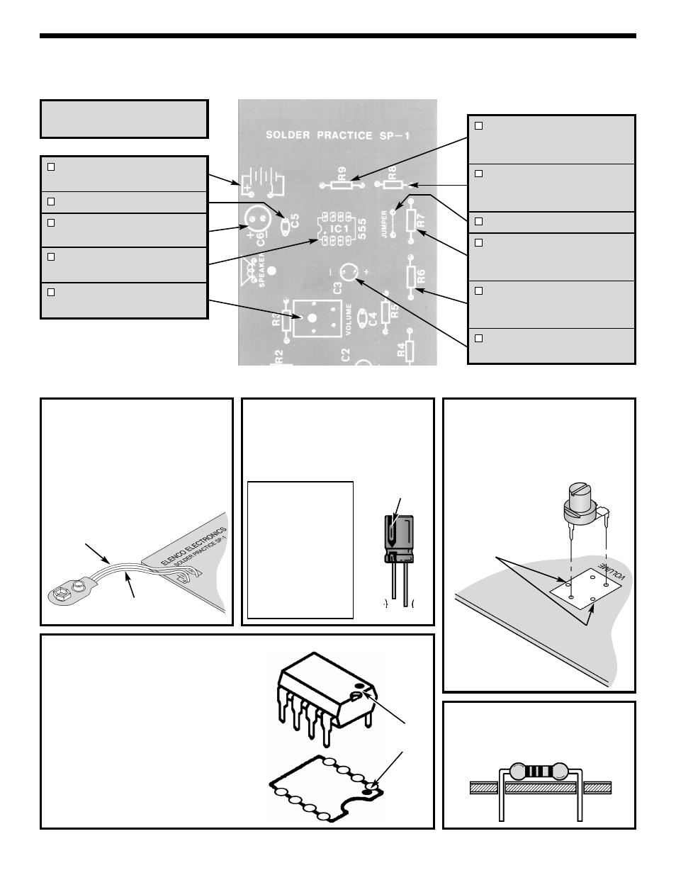
Electrolytic capacitors have polarity.
Be sure to mount them with the
negative (–) lead (marked on side) in
the correct hole.
Warning: If the
capacitor is
connected with
incorrect polarity,
it may heat up
and either leak
or cause the
capacitor to
explode.
PC BOARD ASSEMBLY
NOTE: Before beginning assembly, please refer to page 13 for the resistor reading exercise. This will familiarize
you with the resistor color band coding.
Battery Snap
(see Figure A)
C5 - .02
μF or .022μF Discap
C6 - 100
μF Electrolytic (Lytic)
(see Figure B)
IC1 - 555 or 1455 Timer
(see Figure C)
VR1 - 200
Ω Potentiometer
(see Figure D)
R9 - 10k
Ω 5% ¼W Resistor
(brown-black-orange-gold)
(see Figure E)
R8 - 10k
Ω 5% ¼W Resistor
(brown-black-orange-gold)
(see Figure E)
Jumper Wire (see Figure F)
R7 - 470
Ω 5% ¼W Resistor
(yellow-violet-brown-gold)
(see Figure E)
R6 - 22k
Ω 5% ¼W Resistor
(red-red-orange-gold)
(see Figure E)
C3 - 10
μF Electrolytic (Lytic)
(see Figure B)
Figure E
Mount the resistor flat against the PC
board as shown.
Figure A
Solder the Red Positive (+) lead of
the battery snap to the hole marked
(+) on the PC board. Solder the
Black Negative (–) lead to the hole
marked (–) on the PC board. Cut off
the excess leads.
Figure C
Mount IC1 in the location shown below onto
the PC board. Be sure that the notch or dot
on the IC is in the same direction as the
marking on the PC board (see drawing
below). Solder and cut off the excess leads.
NOTE: Do not keep the soldering iron on the
IC leads for extended periods of time. You
run the risk of overheating the IC, thus
damaging it.
Figure D
Mount VR1 into the three holes in the
PC board as shown below. Note that
the other two holes are not used.
Solder and cut off the excess leads.
Solder the following parts to
the PC board.
Notch
or Dot
Red Wire
Black Wire
Holes Not Used
Polarity
marking
(–)
(+)