Assemble components to the pc board – Elenco 23 Range 20k/V VOM in Kit Form User Manual
Page 6
-5-
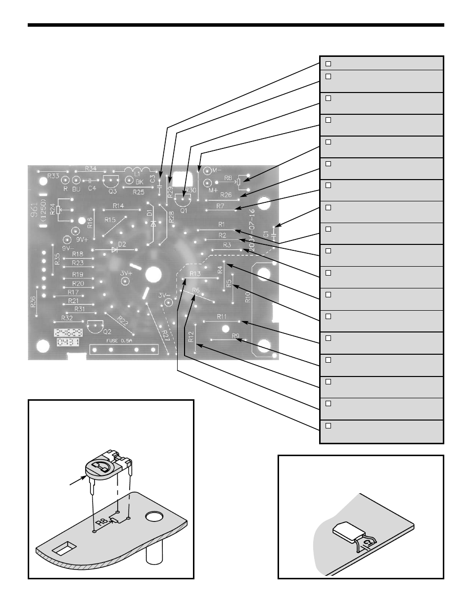
C3 - .047
μF Discap (473)
R29 - 820k
Ω 1% 1/4W Resistor
(gray-red-black-orange-brown)
Q1 - C1815 Transistor
(see Figure C)
R30 - 260k
Ω 1% 1/4W Resistor
(red-blue-black-orange-brown)
R8 - 680
Ω Potentiometer
(see Figure E)
R26 - 31k
Ω 1% 1/4W Resistor
(orange-brown-black-red-brown)
R7 - 240
Ω 1% 1/4W Resistor
(red-yellow-black-black-brown)
C1 - .047
μF 400V (473) Mylar Cap.
(see Figure F)
R1 - 15M
Ω 1% 1/2W Resistor
(brown-green-black-green-brown)
R2 - 4M
Ω 1% 1/2W Resistor
(yellow-black-black-yellow-brown)
R3 - 800k
Ω 1% 1/4W Resistor
(gray-black-black-orange-brown)
R4 - 150k
Ω 1% 1/4W Resistor
(brown-green-black-orange-brown)
R5 - 40k
Ω 1% 1/4W Resistor
(yellow-black-black-red-brown)
R11 - 10
Ω 1% 1/4W Resistor
(brown-black-black-gold-brown)
R9 - .97
Ω 1% 1/2W Resistor
(black-white-violet-silver-brown)
R12 - 102
Ω 1% 1/4W Resistor
(brown-black-red-black-brown)
R6 - 5k
Ω 1% 1/4W Resistor
(green-black-black-brown-brown)
R13 - 3k
Ω 1% 1/4W Resistor
(orange-black-black-brown-brown)
Figure E
Mount the 680
Ω pot to the PC board as
shown. Solder the leads to the foil side of the
PC board.
ASSEMBLE COMPONENTS TO THE PC BOARD
After each step, put a check in the box located next to the step that you have completed.
Figure F
Mount and bend the mylar capacitor as
shown. Solder and cut off the excess leads.
680
Ω Pot