Troubleshooting chart – Elenco 23 Range 20k/V VOM in Kit Form User Manual
Page 13
-12-
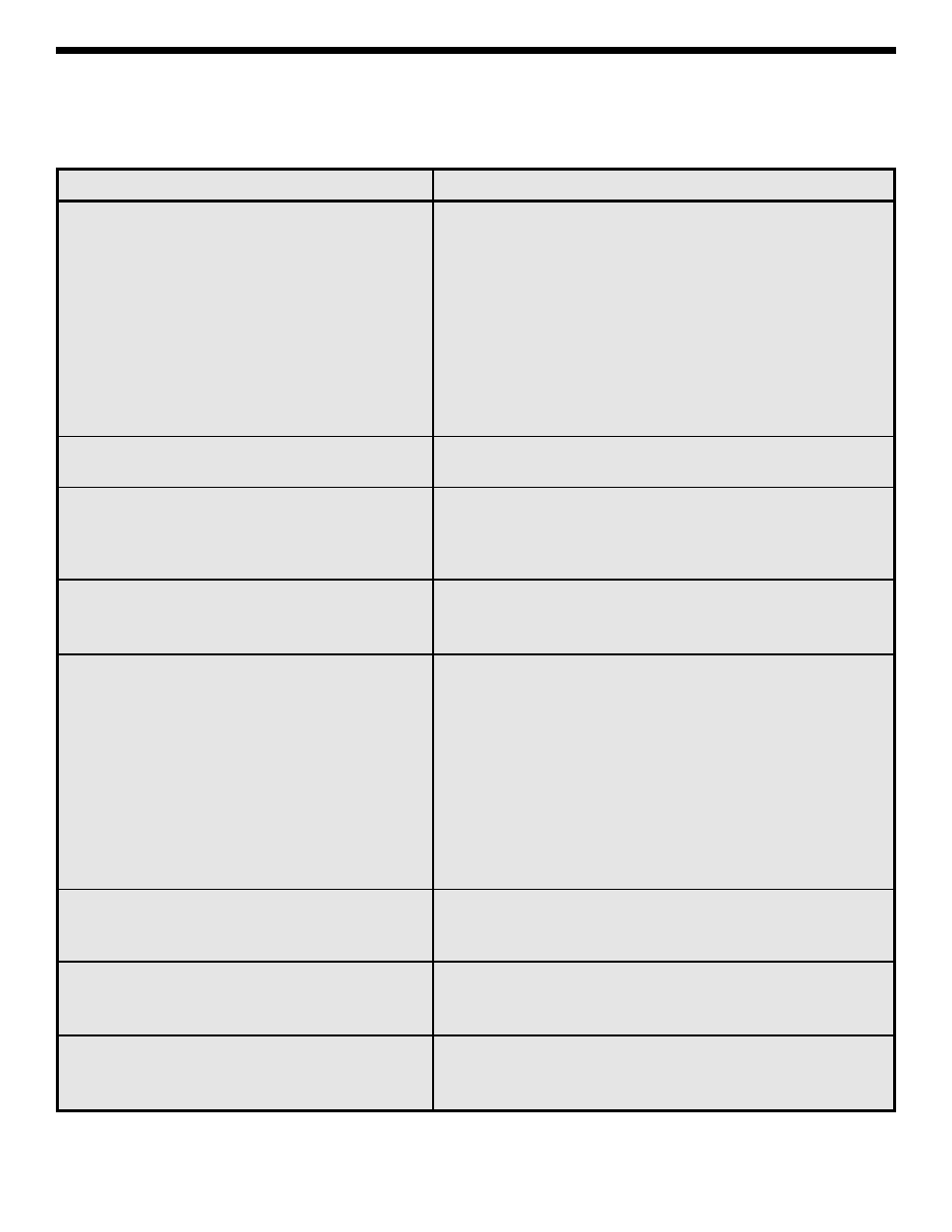
TROUBLESHOOTING CHART
This chart lists the condition and possible causes of several malfunctions. If a particular part is mentioned as
a possible cause, check that part to see if it was installed correctly. Also, check that part and the parts
connected to it for good solder connections.
PROBLEM
POSSIBLE CAUSE
No DC voltage reading
1. Check for open fuse.
Refer to Figure 2 for a better understanding
2. Check resistors R1 - R8, R13 for correct values
of how the meter works.
and good solder connections.
3. Check that the PC board is seated properly and that
the three board clamps are engaged.
4. Check the meter movement. Unsolder the red wire
from the meter movement to the PC board. Place a
75k
Ω resistor between the red wire and the positive
side of a 1.5V battery. Connect the negative side of
the battery to the black wire from the meter movement.
The meter should read a little over half scale.
Wrong meter readings
1. Check resistors R1 - R7, R13, R24 & R25 for correct
values and good solder connections.
No AC voltage reading
1. Check for open fuse.
Refer to Figure 3 for a better understanding
2. Check diodes D1, D2 for opens and shorts.
of how the meter works.
3. Check resistors R8, R14 - R17
for correct values and good solder connections.
No DC current reading
1. Check for open fuse.
Refer to Figure 4 for a better understanding
2. Check resistors R7 - R13 for correct values and good
of how the meter works.
solder connections.
Ohms
1. If meter cannot be zeroed:
Refer to Figure 5 for a better understanding
A. Check for open fuse.
of how the meter works.
B. Check for weak or improperly installed
batteries.
C. Check that the battery snap and battery con-
tacts are installed correctly.
D. Check resistors R23 - R25 for correct value
and good solder connections.
2. If meter does not read correctly:
A. Check R18 - R25 for correct value and good
solder connections.
No h
FE
reading
1. Check resistors R21, R23 - R25, R35, and R36.
Refer to Figure 6 for a better understanding
of how the meter works.
Buzzer not working.
1. Check the following components: R31 - R34, Q2, Q3,
C4, L1, and the fuse for correct values and good solder
connections.
Null not working.
1. Check the following components: R3 - R6, R28 - R30,
Q1, and C3 for correct values and good solder
connections.