Resistance measurements, Figure 5 simplified resistance measurement diagram, Measurement – Elenco 3 1/2 Digit Cap. / Trans. Kit User Manual
Page 5: Figure 6, B) dc/ac current measurement, C) resistance measurement, D) diode test, 3 method of measurement -31
-4-
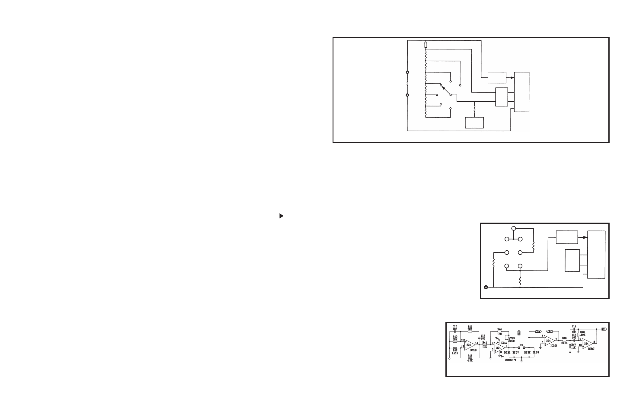
RESISTANCE MEASUREMENTS
Figure 5 shows a simplified diagram of the resistance measurement function.
Figure 5 Simplified Resistance Measurement Diagram
External
Resistor
100
Ω
Voltage
Source
100mV
Ref
Low Pass
Filter
7106
A simple series circuit is formed by the voltage
source, a reference resistor from the voltage divider
(selected by range switches), and the external
unknown resistor. The ratio of the two resistors is
equal to the ratio of their respective voltage drops.
Therefore, since the value of one resistor is known,
the value of the second can be determined by using
the voltage drop across the known resistor as a
reference. This determination is made directly by the
A/D converter.
Overall operation of the A/D converter during a
resistance measurement is basically as described
earlier in this section, with one exception. The
reference voltage present during a voltage
measurement is replaced by the voltage drop
across the reference resistor. This allows the voltage
across the unknown resistor to be read during the
read period. As before, the length of the read period
is a direct indication of the value of the unknown.
h
FE
MEASUREMENT
Figure 6 shows a simplified diagram of the h
FE
measurement function. Internal circuits in the 7106
IC maintain the COMMON line at 2.8 volts below
V+. When a PNP transistor is plugged into the
transistor socket, base to emitter current flows
through resistor R49. The voltage drop in resistor
R49 due to the collector current is fed to the 7106
and indicates the h
FE
of the transistor. For an NPN
transistor, the emitter current through R50 indicates
the h
FE
of the transistor.
Figure 6
The capacitor circuit consists of four op-
amps. IC3 D&A form an oscillator, which is
applied to the test-capacitor through the test
leads. The capacitor couples the oscillator to
pin 6 of IC3B. The amount of voltage
developed at pin 6 is indicative of the
capacitors ESR value. IC3B and C amplify
the signal which is seen at pin 8. The AC
signal is then converted to a DC voltage and
displayed on the meter.
900
Ω
9k
Ω
90k
Ω
900k
Ω
9M
Ω
20M
Ω
2M
Ω
200k
Ω
20k
Ω
2k
Ω
200
Ω
100mV
Ref
Low Pass
Filter
7106
R50
220k
Ω
COM
220k
Ω
10
Ω
PNP
NPN
E
C
B
B
C
E
V+
CAPACITANCE MEASUREMENT
Figure 7
(A) DC/AC Voltage Measurement
1. Connect the red test lead to “V
Ω
CAP” input jack
and the black one to the “COM” jack.
2. Turn the meter on by pressing the power switch.
3. Set the range selector knob to the desired volt
position. If the magnitude of the voltage is not
known, set the range selector knob to the
highest range and reduce until a satisfactory
reading is obtained.
4. Connect the test leads to the device or circuit
being measured.
5. Turn on the power to the device or circuit being
measured. The voltage value will appear on the
digital display along with the voltage polarity.
6. Turn off the power to the device or circuit being
tested and discharge all of the capacitors prior to
disconnecting the test leads.
(B) DC/AC Current Measurement
1. Connect the red test lead to the “A” input jack for
current measurement up to 200mA, and the
black one to “COM”.
2. Turn the meter on by pressing the power switch.
3. Set the range selector knob to the desired “Amp”
current position.
If the magnitude of current is not known, set the
range selector knob to the highest range and
reduce until a satisfactory reading is obtained.
4. Open the circuit to be measured, and connect
the test leads in series with the load in which
current is to be measured.
5. Read the current value on the digital display.
6. Turn off all power to the circuit being tested and
discharge all of the capacitor prior to
disconnecting the test lead.
7. To measure in the 20A range, use the “20A” jack
as the input jack. Be sure to measure within 10
seconds to avoid high-current hazard.
(C) Resistance Measurement
1. Connect red test lead to the “V
Ω
CAP” input jack
and the black one to “COM”.
2. Turn the meter on by pressing the power switch.
3. Set the range selector knob to desired “Ohm”
position.
4. If the resistance being measured is connected to
a circuit, turn off the power to the circuit being
tested and discharge all capacitors.
5. Connect the test leads to the circuit being
measured. When measuring high resistance, be
sure not to contact adjacent point even if
insulated, because some insulators have a
relatively low insulation resistance, causing the
measured resistance to be lower than the actual
resistance.
6. Read resistance value on digital display.
(D) Diode Test
1. Connect the red test lead to “V
Ω
CAP” input jack
and the black one to the “COM” jack.
2. Turn the meter on by pressing the power switch.
3. Set the range selector knob to the “ ”
position.
4. If the semiconductor junction being measured is
connected to the circuit, turn off the power to the
circuit being tested and discharge all of the
capacitors.
5. Connect the test leads to the device and read
forward value on the digital display.
6. If the digital reads overrange (1), reverse the
lead connections.
The placement of the test leads when the
forward reading is displayed indicates the
orientation of the diode.
The red lead is positive and the black lead is
negative.
If overrange (1) is displayed with both lead
connections, the junction is open.
3-3 Method of Measurement
-31-