Operation maintenance, (e) transistor h, Measurement – Elenco 3 1/2 Digit Cap. / Trans. Kit User Manual
Page 33: F) capacitance measurement, Current measurement, 1 battery and fuse replacement, 2 shunt wire calibration
-32-
(E) Transistor h
FE
Measurement
1. The transistor must be out of circuit. Set the
rotary selector knob to the h
FE
position.
2. Turn the meter on by pressing the power switch.
3. Plug the emitter, base and collector leads of the
transistor into the correct holes in either the NPN
of the PNP transistor test socket, whichever is
appropriate for the transistor you are checking.
4. Read the h
FE
(beta or DC current gain) on the
display.
(F) Capacitance Measurement
1. Connect red test lead to the “V
Ω
CAP” input jack
and the black one to “COM”.
2. Turn the meter on by pressing the power switch.
3. Set the rotary selector knob to the “FARAD”
position.
4. Set the rotary selector knob to the desired
capacitance position.
5. Short the leads of the capacitor to be tested
together to insure that there is no charge on the
capacitor.
6. Connect the leads to the capacitor and read the
capacitance value on the digital display.
-3-
VOLTAGE MEASUREMENT
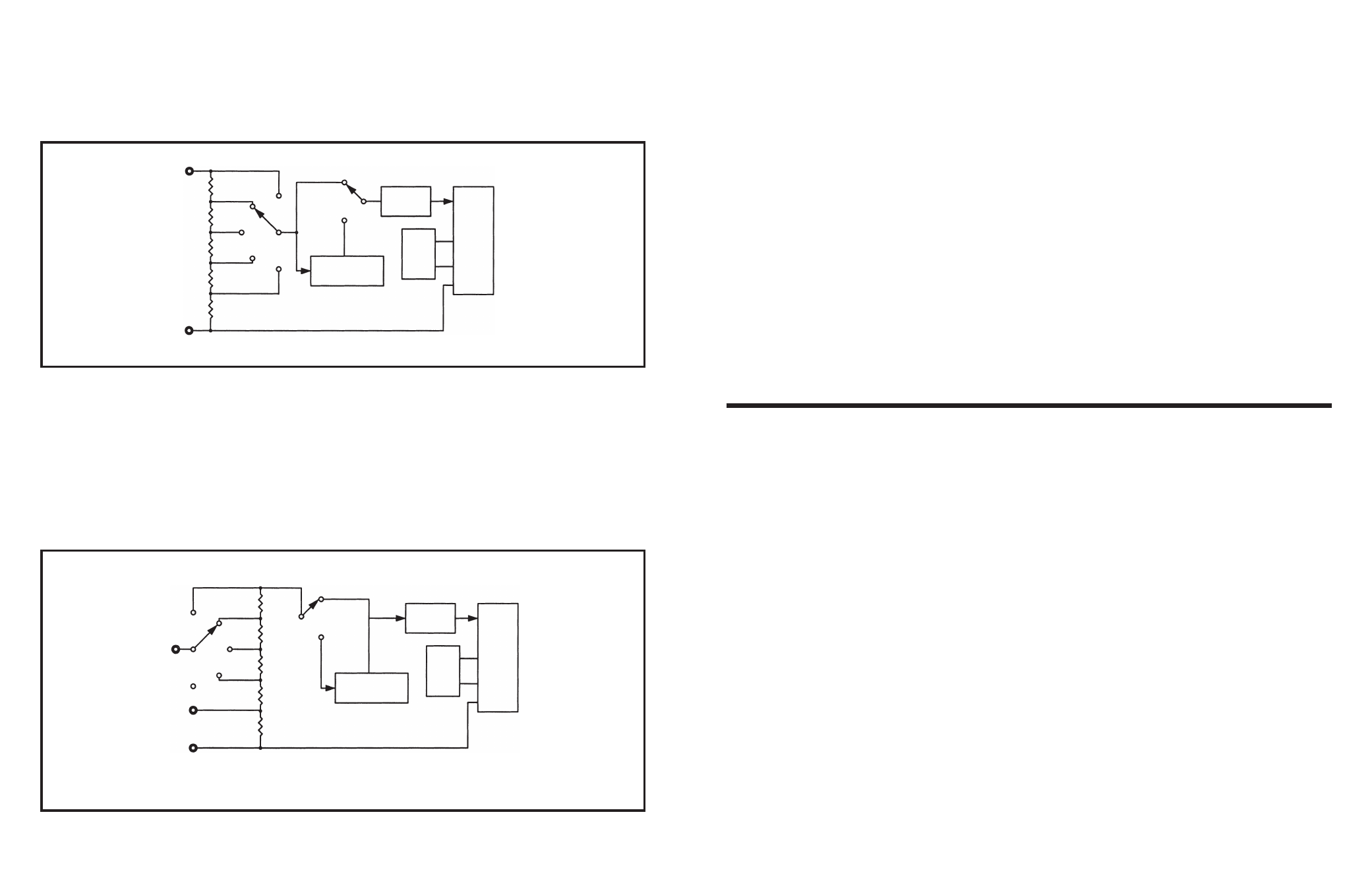
Figure 3 Simplified Voltage Measurement Diagram
Figure 4 Simplified Current Measurement Diagram
200mV
Volts
9M
Ω
900k
Ω
90k
Ω
9k
Ω
9
Ω
Common
750V
200V
20V
2V
AC to DC
Converter
AC
DC
Low Pass
Filter
100mV
Ref
7106
200
μ
A
A
900
Ω
2mA
20mA
200mA
20A
COM
AC - DC
Converter
AC
DC
Low Pass
Filter
100mV
Ref
7106
Figure 3 shows a simplified diagram of the voltage
measurement function.
The input divider resistors add up 10M
Ω
with each
step being a division of 10. The divider output
should be within –0.199 to +0.199V or the overload
indicator will function. If the AC function is selected,
the divider output is AC coupled to a full wave
rectifier and the DC output is calibrated to equal the
rms level of the AC input.
Figure 4 shows a simplified diagram of the current
measurement positions.
Internal shunt resistors convert the current to
between –0.199 to +0.199V which is then
processed in the 7106 IC to light the appropriate
LCD segments. If the current is AC in nature, the AC
converter changes it to the equivalent DC value.
CURRENT MEASUREMENT
90
Ω
9
Ω
0.99
Ω
0.01
Ω
20A
4. OPERATION MAINTENANCE
4-1 Battery and Fuse Replacement
CAUTION
BEFORE ATTEMPTING BATTERY REMOVAL OR
REPLACEMENT, DISCONNECT THE TEST
LEADS FROM ANY ENERGIZED CIRCUITS TO
AVOID SHOCK HAZARD.
The fuse rarely needs replacement and blow almost
always as a result of operator error. To replace the
battery and fuse (200mA/250V), remove the two
screws in the bottom of the case. Simply remove the
old battery or fuse and replace with a new one.
4-2 Shunt Wire Calibration
To calibrate the shunt wire, you will need a 5 amp
current source such as a 5V power supply and a 1
ohm, 25 watt resistor. If a 5 amp source is not
available, you can use a lower current (2 amps). Set
the range switch to the 20A position and connect the
test leads.
If the meter reads higher than 5A, resolder the shunt
wire so that there is less wire between the two
mounting holes.
If the meter reads low, resolder the shunt wire so
that there is more wire between the two mounting
holes.