Operation, Transistor h, Diode test – Elenco 3 1/2 Digit Cap. / Trans. Kit User Manual
Page 31: 1 preparation and caution before measurement -30, Range test condition npn 2ma 3v pnp 2ma 3v
Transistor h
FE
Range
Test Condition
NPN
2mA 3V
PNP
2mA 3V
Diode Test
Measures forward resistance of a semiconductor junction in k Ohm at max. test current of 1mA.
3. OPERATION
3-1 Preparation and caution before measurement
-30-
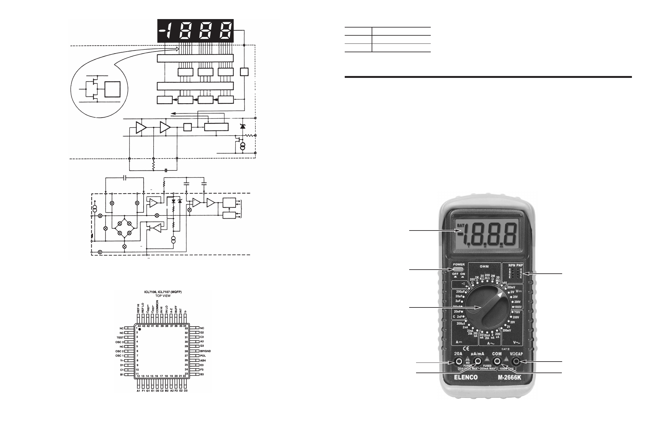
LCD Display
Range Selector Knob
20A Input Jack
(200mA Max) A input Jack
On/Off Switch
h
FE
Input Socket
Volt Ohm Cap Input Jack
Common Input Jack
1. If the function must be switched during a
measurement, always remove the test leads
from the circuit being measured.
2. If the unit is used near noise generating
equipment, be aware that the display may
become unstable or indicate large errors.
3. Avoid using the unit in places with rapid
temperature variations.
4. In order to prevent damage or injury to the unit,
never fail to keep the maximum tolerable voltage
and current, especially for the 20A current range.
5. Carefully inspect the test lead. If damaged,
discard and replace.
3-2 Panel Description
-5-
Figure 8 7106 Functions
a
b
a
b
c
d
e
f
g
TYPICAL SEGMENT OUTPUT
0.5mA
2mA
V+
Segment
Output
Internal Digital Ground
LCD PHASE DRIVER
LATCH
7 Segment
Decode
7 Segment
Decode
7 Segment
Decode
Thousand
Hundreds
Tens
Units
*
CLOCK
To Switch Drivers
From Comparator Output
-4
LOGIC CONTROL
Internal Digital Ground
200
BACKPLANE
28
V+
TEST
V
500
Ω
3
34
6.2V
1V
* Three inverters.
One inverter shown for clarity.
7
6
4
OSC 1
OSC 2
OSC 3
DIGITAL SECTION
ANALOG SECTION of 7106
C
REF
R
INT
C
AZ
C
INT
INT
C
REF
+
REF HI
REF LO C
REF
BUFFER
V+
35
42
44
43
41
36
37
8
AUTO
ZERO
+
A-Z &
Z1
A-Z &
Z1
A-Z
DE (+)
DE (+)
DE (-)
DE (-)
IN HI
COMMON
IN LO
40
39
INT
10
μ
A
V+
38
INT
+
+
+
2.8V
A-Z & DE(+)
& Z1
34
V
Z1
6.2V
A-Z
COMPARATOR
ZERO
CROSSING
DETECTOR
POLARITY
FLIP/FLOP
TO
DIGITAL
SECTION
INTEGRATOR
a
b
c
d
e
f
g
a
b
c
d
e
f
g