Assemble components to the pc board – Elenco Logic Probe Kit User Manual
Page 8
-7-
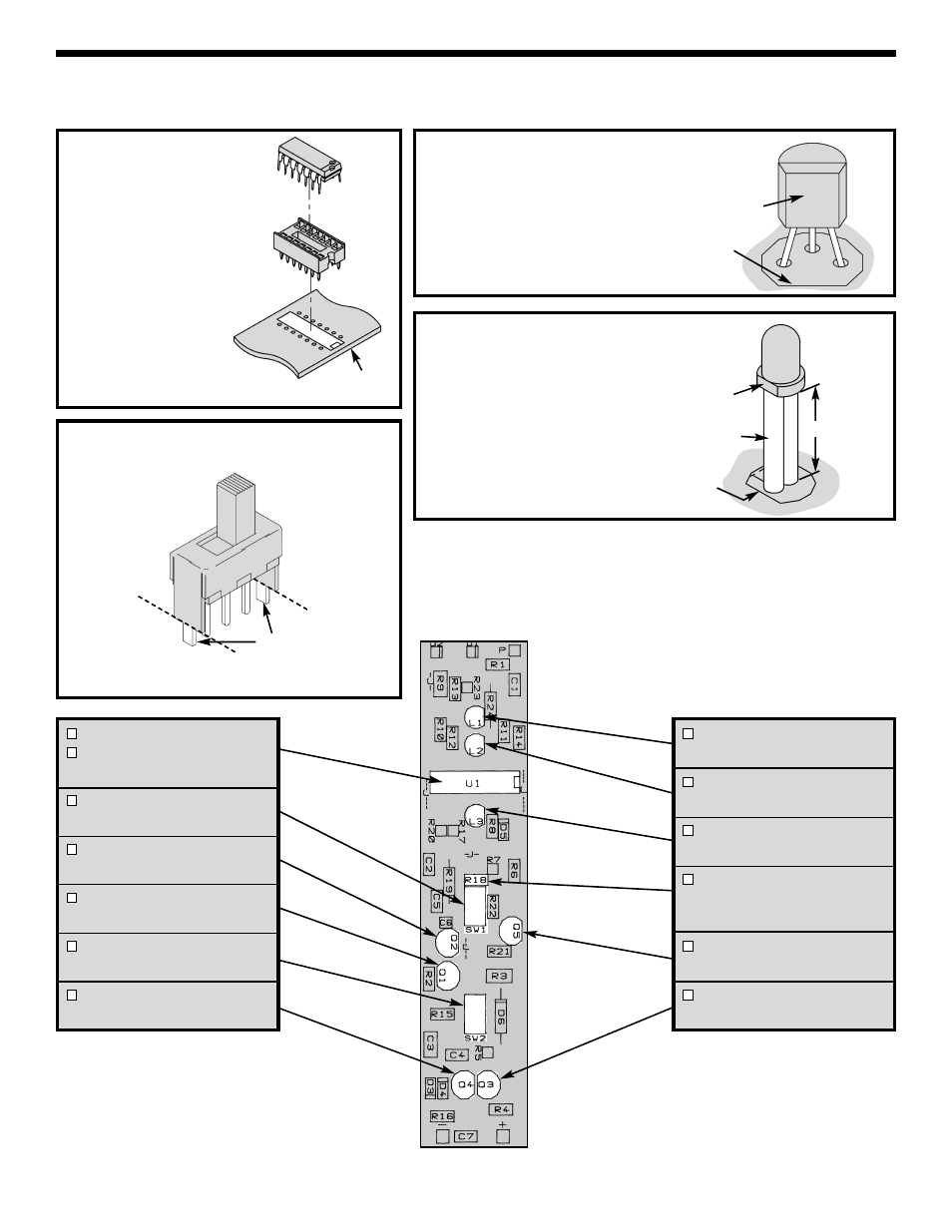
ASSEMBLE COMPONENTS TO THE PC BOARD
Refer to the top legend on the PC board, install and solder the following components.
Cut a 3/8” piece of tubing for each
LED lead, to be used as stand-offs.
Mount the LED with the flat side in
the direction shown on the top
legend.
Figure 8
L1 - LED
(see Figure 8)
L2 - LED
(see Figure 8)
L3 - LED
(see Figure 8)
R18 - 150kΩ Resistor
(brown-green-yellow-gold)
Install SW1 first.
Q5 - 2N3906 Transistor
(see Figure 7)
Q3 - 2N3906 Transistor
(see Figure 7)
U1 - 14-pin IC Socket
U1 - LM2901 IC
(see Figure 5)
SW1 - Switch
(see Figure 6)
Q2 - 2N3904 Transistor
(see Figure 7)
Q1 - 2N3906 Transistor
(see Figure 7)
SW2 - Switch
(see Figure 6)
Q4 - 2N3904 Transistor
(see Figure 7)
Flat
Side
Tubing
Before installing, snip off the tabs. Mount the
switch so that the legs are touching the PC
board.
Figure 6
}
{
Tab
Leg
Cut off tabs
Insert the IC socket
into the PC board
with the notch in the
direction shown on
the
top
legend.
Solder the IC socket
into place. Insert the
IC into the socket
with the notch in the
same direction as the
notch on the socket.
Figure 5
Socket
IC
PC Board
3/8”
Flat Side
Marking
Figure 7
Mount the transistor with the flat side in the
direction shown on the top legend. Leave
1/4” between the part and PC board.
Flat
Side
Flat Side Marking