Assemble components to the pc board – Elenco One Button Bandit User Manual
Page 6
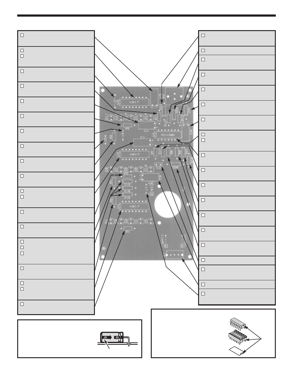
ASSEMBLE COMPONENTS TO THE PC BOARD
-5-
Figure A
Electrolytic capacitors have polarity. Be sure
to mount them with the negative (–) lead
(marked on side) in the correct hole. Mount
the electrolytics horizontal to the PC board.
Bend the leads at right angles and then
insert the leads into the PC board.
C5 - 1
m
F Electrolytic Cap.
(see Figure A)
U3 - 16-pin IC Socket
U3 - 4017 Integrated Circuit
(see Figure B)
J4 - Jumper Wire
(see Figure C)
R11 - 4.7M
W
5% 1/4W Resistor
(yellow-violet-green-gold)
C4 - 1
m
F Electrolytic Cap.
(see Figure A)
R5 - 220
W
5% 1/4W Resistor
(red-red-brown-gold)
J3 - Jumper Wire
(see Figure C)
J2 - Jumper Wire
(see Figure C)
R6 - 100k
W
5% 1/4W Resistor
(brown-black-yellow-gold)
C1 - 1
m
F Electrolytic Cap.
(see Figure A)
U2 - 16-pin IC Socket
U2 - 4017 Integrated Circuit
(see Figure B)
R3 - 220
W
5% 1/4W Resistor
(red-red-brown-gold)
R4 - 100k
W
5% 1/4W Resistor
(brown-black-yellow-gold)
D19 - 1N4148 Diode
D18 - 1N4148 Diode
D16 - 1N4148 Diode
(see Figure D)
R2 - 100k
W
5% 1/4W Resistor
(brown-black-yellow-gold)
U1 - 16-pin IC Socket
U1 - 4017 Integrated Circuit
(see Figure B)
R1 - 220
W
5% 1/4W Resistor
(red-red-brown-gold)
D22 - 1N4148 Diode
(see Figure D)
S2 - Push Button Switch
R12 - 2.2M
W
5% 1/4W Resistor
(red-red-green-gold)
D23 - 1N4148 Diode
(see Figure D)
R13 - 1M
W
5% 1/4W Resistor
(brown-black-green-gold)
D24 - 1N4148 Diode
(see Figure D)
C6 - 1
m
F Electrolytic Cap.
(see Figure A)
U4 - 14-pin IC Socket
U4 - MC14584 or CD40106 IC
(see Figure B)
R7 - 100k
W
5% 1/4W Resistor
(brown-black-yellow-gold)
D17 - 1N4148 Diode
(see Figure D)
R10 - 1k
W
5% 1/4W Resistor
(brown-black-red-gold)
D21 - 1N4148 Diode
(see Figure D)
R9 - 1M
W
5% 1/4W Resistor
(brown-black-green-gold)
D20 - 1N4148 Diode
(see Figure D)
R8 - 18k
W
5% 1/4W Resistor
(brown-gray-orange-gold)
C2 - .1
m
F Discap (104)
C3 - 4.7
m
F Electrolytic Cap.
(see Figure A)
S1 - Slide Switch
J1 - Jumper Wire
(see Figure C)
Figure B
Insert the IC socket into the PC board with
the notch in the direction shown on the top
legend.
Solder the IC socket into place.
Insert the IC into the socket with the notch
in the same direction as the notch on the
socket.
Polarity Marking
Notch