Identifying capacitor values, Identifying resistor values, Introduction theory of operation – Elenco One Button Bandit User Manual
Page 3
The One Button Bandit is better known in Las Vegas
as the One Arm Bandit. Our device has no arms,
but instead a button. Therefore, we call it the One
Button Bandit.
The One Button Bandit is a simplified version of an
electronic slot machine. It contains three columns of
five light emitting diodes (LED). When the switch S2
is pressed, the LEDs will flash on and off
accompanied by sound.
When the bandit stops,
only one LED in each column will remain lit. If three
green LEDs light up, you win the jackpot
accompanied by sound.
-2-
IDENTIFYING CAPACITOR VALUES
Capacitors will be identified by their capacitance value in pF (picofarads), nF (nanofarads), or
m
F (microfarads).
Most capacitors will have their actual value printed on them. Some capacitors may have their value printed in
the following manner.
Second Digit
First Digit
Multiplier
Tolerance
The above value is 10 x 1,000 = 10,000pF or .01
m
F The letter K indicates a tolerance of +10% The letter J indicates a tolerance of +5%
For the No.
0
1
2
3
4
5
8
9
Multiply By
1
10
100
1k
10k 100k
.01
0.1
Multiplier
Note: The letter “R” may be used at times to
signify a decimal point; as in 3R3 = 3.3
10
m
F 16V
IDENTIFYING RESISTOR VALUES
Use the following information as a guide in properly identifying the value of resistors.
BAND 1
1st Digit
Color
Digit
Black
0
Brown
1
Red
2
Orange
3
Yellow
4
Green
5
Blue
6
Violet
7
Gray
8
White
9
BAND 2
2nd Digit
Color
Digit
Black
0
Brown
1
Red
2
Orange
3
Yellow
4
Green
5
Blue
6
Violet
7
Gray
8
White
9
Multiplier
Color
Multiplier
Black
1
Brown
10
Red
100
Orange
1,000
Yellow
10,000
Green
100,000
Blue
1,000,000
Silver
0.01
Gold
0.1
Resistance
Tolerance
Color
Tolerance
Silver
+10%
Gold
+5%
Brown
+1%
Red
+2%
Orange
+3%
Green
+.5%
Blue
+.25%
Violet
+.1%
Bands
1
2
Multiplier
Tolerance
103K
100
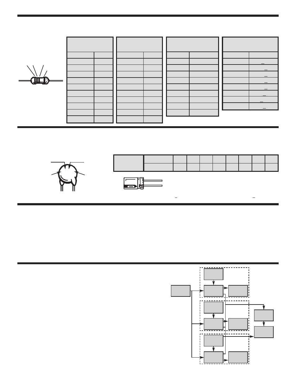
INTRODUCTION
THEORY OF OPERATION
Figure 1 shows the block diagram of the One Button
Bandit.
This block diagram consists of three
identical circuits: (the basic has a timer, a decade
counter, and five LEDs), the Clock Oscillator, the
Sound Circuit and the Key of Ring.
Timer
Counter
Timer
Counter
Timer
Counter
LEDs
Clock
Key
Ring
Sound
Circuit
LEDs
LEDs
1
2
3
Figure 1