Assemble components to the pc board – Elenco Pocket Dice User Manual
Page 7
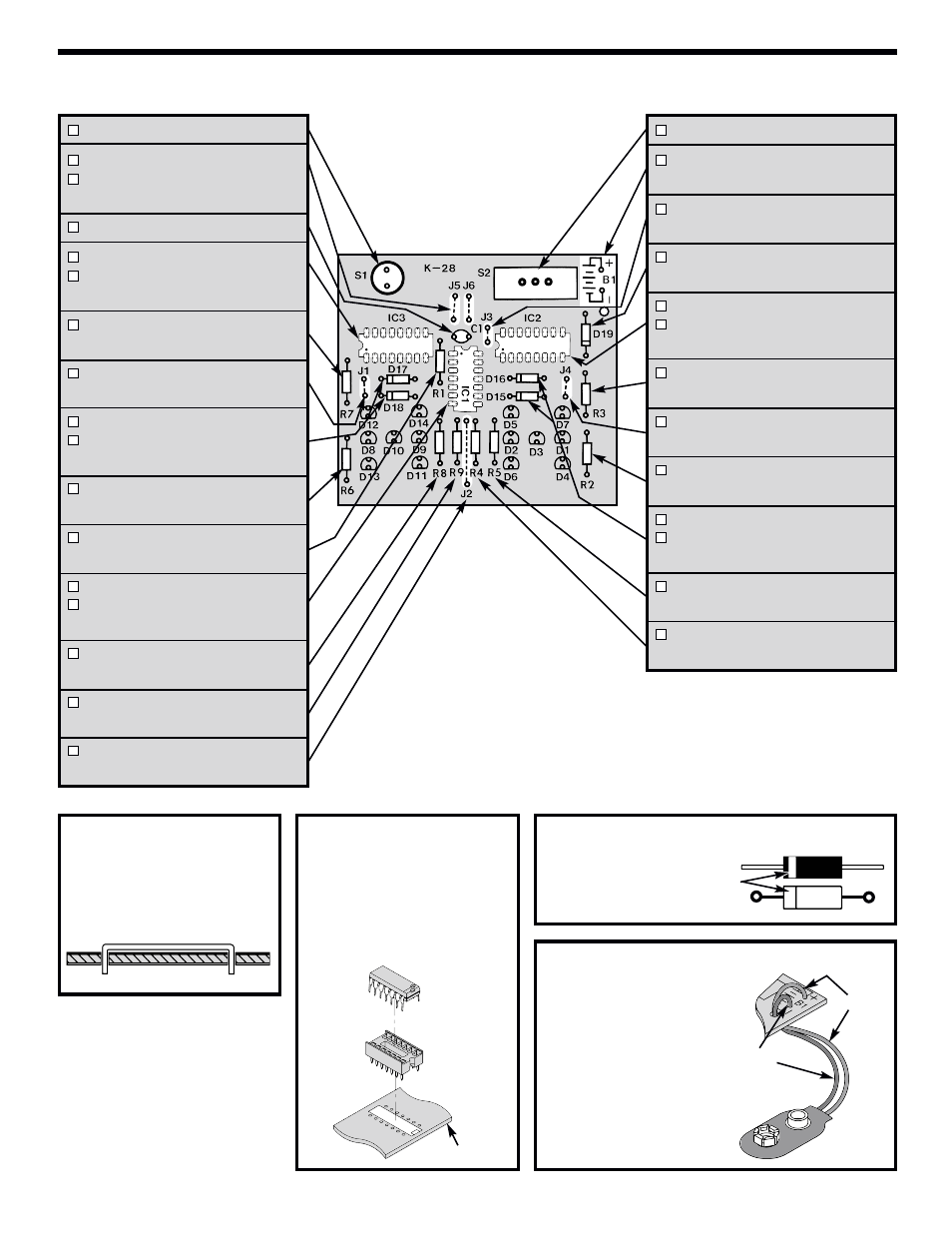
ASSEMBLE COMPONENTS TO THE PC BOARD
Figure C
Mount the diode with
the band in the same
direction shown on PC
board.
Band
S2 - Slide Switch
B1 - Battery Snap 9V
(see Figure D)
J3 - Jumper Wire
(see Figure A)
D19 - 1N4001 Diode
(see Figure C)
IC2 - 16-pin Socket
IC2 - 4018 Integrated Circuit
(see Figure B)
R3 - 1.5kΩ 5% 1/4W Resistor
(brown-green-red-gold)
J4 - Jumper Wire
(see Figure A)
R2 - 1.2kΩ 5% 1/4W Resistor
(brown-red-red-gold)
D16 - 1N4148 Diode
D15 - 1N4148 Diode
(see Figure C)
R5 - 1.2kΩ 5% 1/4W Resistor
(brown-red-red-gold)
R4 - 1.2kΩ 5% 1/4W Resistor
(brown-red-red-gold)
S1 - Push Button Switch
J5 - Jumper Wire
J6 - Jumper Wire
(see Figure A)
C1 - .01µF (103) Capacitor
IC3 - 16-pin Socket
IC3 - 4018 Integrated Circuit
(see Figure B)
R7 - 1.5kΩ 5% 1/4W Resistor
(brown-green-red-gold)
J1 - Jumper Wire
(see Figure A)
D17 - 1N4148 Diode
D18 - 1N4148 Diode
(see Figure C)
R6 - 1.2kΩ 5% 1/4W Resistor
(brown-red-red-gold)
R1 - 100kΩ 5% 1/4W Resistor
(brown-black-yellow-gold)
IC1 - 14-pin Socket
IC1 - 4011 Integrated Circuit
(see Figure B)
R8 - 1.2kΩ 5% 1/4W Resistor
(brown-red-red-gold)
R9 - 1.2kΩ 5% 1/4W Resistor
(brown-red-red-gold)
J2 - Jumper Wire
(see Figure A)
-6-
Figure A
Use a discarded resistor lead
for a jumper wire. Bend the
wire to the correct length and
mount it to the PC board.
Figure B
Insert the IC socket into the PC
board with the notch in the
direction shown on the top
legend. Solder the IC socket into
place. Insert the IC into the
socket with the notch in the same
direction as the notch on the
socket.
Figure D
Mount the battery snap
to B1 on the PC board
as shown below with
the red wire in the (+)
hole and the black wire
in the (–) hole.
Socket
IC
PC Board
Red Wire
Black Wire